
 Tiếng Việt
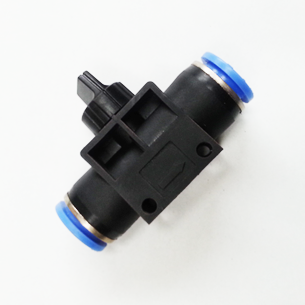

HVU Hand Valve (Union Straight) — Technical Guide for Pneumatic Isolation and Safe Venting
The HVU Hand Valve (Union Straight) is a manually operated, three-way pneumatic valve designed to isolate compressed-air supply lines and safely vent residual pressure to atmosphere. Engineered for simple on/off control, the HVU is widely used across industrial automation, machine tools, packaging equipment, and maintenance isolation points where a dependable, human-operated isolation device is required. This article provides a complete technical overview, specifications, materials and build details, application guidance, installation and maintenance instructions, and comparative analysis with similar valves—formatted and ready for WordPress publication.
Introduction
Effective isolation and safe venting of compressed-air systems are fundamental to personnel safety, machine maintenance, and process integrity. The HVU Hand Valve (Union Straight) addresses both requirements through a compact, three-way design that blocks incoming air while simultaneously venting the downstream volume to atmosphere when set to the “off” position. Because it is designed specifically for compressed air, the HVU offers a controlled, predictable venting path and robust operation across typical pneumatic system pressures and temperatures.
This technical guide is intended for engineers, maintenance technicians, system integrators, and procurement professionals who need a deep understanding of the HVU’s operation, installation considerations, performance characteristics, and lifecycle management.
Technical Overview
At its core, the HVU Hand Valve performs two fundamental functions:
- On/Off isolation: Allows an operator to shut off compressed-air supply to downstream equipment via a simple manual handle action.
- Safe venting: When moved to the off position, the valve vents trapped downstream air to atmosphere while preventing re-pressurization from the supply side.
The HVU family is configured as a three-way union-straight valve: the supply (inlet) and output (outlet) are collinear (straight) and the third port vents to atmosphere. The union connection enables easy disassembly or tubing removal without disturbing the piping, enabling maintenance and replacement in-line.
Key performance envelopes for the HVU Hand Valve are:
- Operating pressure: 0–150 PSI (0–9.9 kgf/cm²; approx. 0–990 kPa)
- Vacuum capability: down to -29.5 in Hg (approx. -750 mm Hg / ~10 Torr)
- Operating temperature range: 0–60°C (32–140°F)
- Intended medium: compressed air only
The valve is available in tube-size pairs (φD1–φD2) to match common pneumatic tubing sizes in both metric (6, 8, 10, 12 mm) and inch equivalents (1/4″, 5/16″, 3/8″, 1/2″). Sample model codes include HVU 06-06, HVU 08-06, HVU 10-08, HVU 12-12, etc.
Operating Principle
The HVU uses a rotary handle linked to an internal spool or ball/plug element that aligns or blocks the straight-through passage. In the open position the supply path is uninterrupted and flow occurs from inlet to outlet. In the off position the internal element seals against the supply port and opens the downstream chamber to the vent port—allowing residual air to escape to atmosphere while preventing supply-side pressurization. Because the vent port opens only when the valve is in the off position, accidental re-pressurization during maintenance is prevented.
Union-Straight Geometry
The “union-straight” designation describes two characteristics:
- Straight flow path: The inlet and outlet are collinear and aligned for simple inline replacement without flow direction changes.
- Union connection: Each end is fitted with a union-style interface (often push-in or threaded union collar) allowing rapid disassembly of tubing from the valve body without removing the valve from the pipeline. This facilitates maintenance, cleaning, or valve replacement with minimum downtime.
Specifications and Dimensions
The table below summarizes the HVU Hand Valve’s key technical specifications and representative dimensional data. Exact physical dimensions vary with model and manufacturer; the values below are representative for typical union-straight hand valves in this family. Always confirm specific part dimensions with the supplier’s datasheet before installation.
| Attribute | HVU 06-06 | HVU 08-08 | HVU 10-10 | HVU 12-12 |
|---|---|---|---|---|
| Tube Connection (nominal) | 6 mm – 6 mm (≈1/4″–1/4″) | 8 mm – 8 mm (≈5/16″–5/16″) | 10 mm – 10 mm (≈3/8″–3/8″) | 12 mm – 12 mm (≈1/2″–1/2″) |
| Operating Pressure | 0–150 PSI (0–9.9 kgf/cm²; ≈0–990 kPa) | |||
| Vacuum Rating | Down to -29.5 in Hg (≈ -750 mm Hg / ~10 Torr) | |||
| Operating Temperature | 0–60°C (32–140°F) | |||
| Port Type | Union push-in / union-threaded (model dependent) | |||
| Material (typical) | Brass or aluminum body, PBT/PA union collet, NBR/EPDM seals | |||
| Body Length (L) | ~55 mm | ~60 mm | ~68 mm | ~75 mm |
| Overall Height (handle up) | ~45 mm | ~48 mm | ~52 mm | ~55 mm |
| Weight (approx.) | ~35 g | ~45 g | ~65 g | ~85 g |
Note: Dimensions labeled with “~” are approximate and intended for planning purposes only. For panel cutouts, clearance and mounting details, consult the manufacturer’s dimensional drawing for the exact model.
Materials and Build Quality
Although the HVU Hand Valve family is produced in multiple variants to suit application cost and environment, the following materials and build techniques are common. Where manufacturers produce different material options, the technical differences impact durability, compatibility, and performance in specific environments.
Typical Component Materials
- Valve Body: Commonly made from nickel-plated brass, brass, or die-cast aluminum. Nickel plating improves corrosion resistance and extends life in mildly corrosive environments. Some lower-cost versions use engineered polymers (e.g., glass-filled nylon, PBT) for corrosion resistance and reduced weight.
- Handle: Anodized aluminum or zinc die-cast with thermoplastic (PP/POM) overmold for operator comfort and insulation. Handles are designed for tactile feedback and clear open/close orientation.
- Seals and O-rings: NBR (nitrile rubber) is common for general-purpose compressed-air service due to good wear resistance and compatibility with oil-lubricated air. EPDM is used where compatibility with water or higher temperature tolerance is required. FKM (Viton) is less common due to cost and limited suitability in some air systems.
- Union Collet / Push-Fit Components: Typically made from PBT or PA (nylon) for dimensional stability, with stainless steel or brass retainers for the tubing gripping teeth.
- Internal Spool / Plug: Machined brass, stainless steel, or engineered plastic, depending on model. Metal internals yield high durability and repeatability; polymer internals reduce cost and weight.
- Fasteners & Springs: Stainless steel for corrosion resistance when exposed to moisture or periodic washdown.
Build Quality Considerations
Selecting the appropriate material set is a trade-off among cost, corrosion resistance, mechanical robustness, and operating environment. For heavy industrial use, nickel-plated brass or stainless-steel internals combined with EPDM seals offer extended life in humid and oily environments. For clean-room or dry-room applications where metallic contamination must be minimized, engineered plastic bodies and non-metallic internals may be preferred.
Manufacturing tolerances for valve seats and sealing faces are critical: tight machined tolerances ensure reliable shutoff at the low side of the pressure range and reduce the risk of leak-through. Quality valves typically present a bubble-tight shutoff to the leakage limit specified in the datasheet (e.g., <1 x 10^-4 mbar·l/s typical for compressed air valves).
Key Features
The HVU Hand Valve incorporates features that make it effective and easy to deploy across industrial pneumatic systems. Below are the primary features and what each contributes to system performance.
- Three-way venting: Automatically vents downstream pressure to atmosphere when switchedoff, preventing trapped energy during maintenance.
- Union-style connections: Quick disconnection and reconnection of tubing, simplifying replacement and maintenance without disturbing the rest of the system.
- Straight-through flow: Minimal disruption of flow path and predictable pressure drop characteristics for system modelling.
- Ergonomic handle: Clear positional indication and comfortable manual operation; suitable for frequent switching actions.
- Wide availability of tube sizes: Metric and inch size options facilitate installation in systems worldwide.
- Vacuum capability: Rated to near full vacuum, allowing use in both positive-pressure and low-pressure vacuum applications within the rated envelope.
- Compact footprint: Small size makes the valve suitable for installation in tight manifolds and control panels.
Use Cases and Applications
The HVU Hand Valve is versatile and finds utility across many pneumatic system scenarios. Below are use cases grouped by industry and application type:
Manufacturing & Automation
- Isolation of pneumatic actuators or tooling stations during setup or changeover.
- Local emergency or maintenance isolation points on complex manifolds.
- Service ports for test instrumentation and flow checks.
Packaging & Food Processing
- Manual isolation for packaging lines requiring frequent maintenance or cleaning cycles (select polymer-bodied valves where washdown compatibility is required).
- Venting sections of line during product changeovers to prevent product contamination.
Robotics & Assembly Cells
- Isolating end-effectors and pneumatic grippers for safe repair and tool changes.
- Local de-pressurization of pneumatic fixtures prior to mechanical adjustment.
Laboratory & Test Benches
- Manual venting for controlled release of pressure during experimentation.
- Integration into test rigs where quick isolation and venting are required between trials.
Maintenance & Safety
- Lockout-Tagout (LOTO) point for compressed-air lines (combine with appropriate safety lockout plates or padlocks where available).
- Interim isolation for service procedures to ensure residual pressure is eliminated before entry into equipment.
Comparison with Similar Valves
To place the HVU Hand Valve in context, the following table compares the HVU with common alternative isolation devices: a standard 2-way shutoff valve (no vent), a ball valve with in-line porting, and a quick exhaust valve (QE).
| Characteristic | HVU Hand Valve (3-way union-straight) | 2-Way Shutoff Valve (inline) | Ball Valve (metal, inline) | Quick Exhaust Valve (QE) |
|---|---|---|---|---|
| Venting capability | Yes — vents downstream to atmosphere when off | No — traps downstream pressure unless separately vented | No — traps pressure (unless a dedicated vent port exists) | Yes — used to rapidly vent cylinder exhaust to atmosphere |
| Recommended use | Maintenance isolation points, local venting | General shutoff where venting not required | High-flow shutoff and isolation | Speeding cylinder exhaust, not for isolation |
| Flow capacity | Moderate (size-dependent) | Moderate | High (full-bore ball valves available) | High exhaust flow (in one direction) |
| Suitable for vacuum | Yes (rated to -29.5 in Hg) | Some models yes, many not rated | Depends on packing/seat | No — not intended for vacuum isolation |
| Ease of disassembly | High — union connections | Medium — threaded/union options | Low–Medium (requires tools) | Low — usually integrated inline |
| Best for LOTO | Yes (with lockable handle options) | Yes (if lockable) | Yes (lockable handles common) | No — not intended for isolation |
This comparison highlights the HVU’s niche as an isolation valve with integrated safe venting, making it preferable for maintenance access points compared to standard 2-way shutoffs or flow-focused ball valves.
Benefits and Limitations
Benefits
- Safety: The built-in venting eliminates trapped pressure in downstream components when set to off, reducing risk to maintenance personnel.
- Convenience: Union-style connections and compact size allow straightforward retrofits and minimal downtime for replacement.
- Versatility: Compatible with a wide range of pneumatic tubing sizes and both metric and inch systems.
- Vacuum-capable: Supports both pressurized air and near full vacuum applications, expanding use cases beyond positive-pressure only systems.
- Clear indication: Manual handle provides explicit visible and tactile indication of the valve state.
Limitations
- Medium restriction: The valve is intended for compressed air only. Use with other gases or fluids may degrade seals or create hazards.
- Flow capacity: Although adequate for many pneumatic control tasks, the HVU’s flow capacity is lower than full-bore ball valves; not ideal where high flow and minimal pressure drop are required.
- Temperature limits: Typical operating range (0–60°C) may preclude hot-air or elevated-temperature service unless higher-temperature seal options are specified.
- Leak potential: As with any manual valve, older seals or improper installation can lead to leakage. Regular inspection and maintenance are necessary.
Installation Guidelines
Proper installation ensures valve longevity and trouble-free operation. Use the following professional practices when installing an HVU Hand Valve:
- Verify compatibility: Confirm valve bore and tube sizes match system tubing. Ensure seal material compatibility with any lubricants in the air supply.
- Isolate and depressurize: Before installation, isolate the affected section and fully depressurize the line. Use lockout-tagout (LOTO) procedures when required.
- Check tubing: Cut tubing squarely and deburr the end. For push-in union connections, ensure the tubing is free from nicks and clean.
- Insert tubing fully: For push-fit unions, insert the tubing until it seats against the stop. Pull back gently to confirm retention.
- Orientation: Install so the handle is accessible for operator use and with sufficient clearance for the vent to safely discharge away from personnel and sensitive equipment.
- Mounting support: Support piping and tubing near the valve to avoid load on the union fittings, which could cause leaks or premature wear.
- Tightening (threaded unions): For threaded union options, use appropriate thread sealant on male threads and torque to supplier specifications to avoid over-tightening which can distort sealing faces.
- Verify operation: After installation, pressurize the system slowly and check for leaks at the unions and body. Cycle the valve several times to confirm on/off and venting behavior.
- Lockable options: If the valve will be used for lockout/tagout, install a padlock-compatible locking accessory (if provided) in accordance with the supplier instructions.
Placement and Venting Considerations
When the valve vents to atmosphere, the discharged air may contain oil, condensation, or particulates. Orient the valve so the vent does not discharge onto operators, electrical panels, or sensitive components. If necessary, direct vented air into a safe capture device or muffler with a drain path for condensate.
Flow Characteristics and Performance Considerations
Understanding the HVU’s flow behavior is important for system sizing and predicting pressure loss. Flow capacity is typically described by Cv or Kv coefficients. Because the HVU is a compact union-straight valve, its Cv will be lower than large full-bore ball valves. Below is a representative, approximate table of Cv values for common HVU sizes. These values are for estimation only—refer to manufacturer datasheets for precise coefficients.
| Model | Nominal Tube Size | Estimated Cv (approx.) | Representative Free-Bore Diameter |
|---|---|---|---|
| HVU 06-06 | 6 mm (1/4″) | ~0.05 – 0.12 | ≈ 2.5–3.0 mm |
| HVU 08-08 | 8 mm (5/16″) | ~0.12 – 0.25 | ≈ 3.0–4.0 mm |
| HVU 10-10 | 10 mm (3/8″) | ~0.25 – 0.5 | ≈ 4.5–5.5 mm |
| HVU 12-12 | 12 mm (1/2″) | ~0.5 – 1.0 | ≈ 6.0–7.0 mm |
These Cv values suggest that for modest volumetric flow rates typical in control and instrument lines, the HVU will provide adequate flow. For applications demanding high mass flow (large actuators or multiple simultaneous cylinder operations), a full-bore ball valve or larger pipeline may be more appropriate.
Pressure Drop Example (Illustrative)
As an example calculation: For a short pressure drop estimation using Cv, the standard liquid equation is not directly used for compressed air; however, practitioners commonly use approximate relationships for sizing. If an HVU 10-10 with Cv=0.4 is installed and the system requires 10 SCFM at 80 PSI supply, the pressure drop across the valve would be small but non-zero. Because pneumatic flow calculations are sensitive to compressibility and piping, engineers should use industry-standard flow/pressure calculators or manufacturer curves for precise estimates.
If higher accuracy is required during design, request manufacturer flow vs. pressure-drop curves or perform bench testing with your actual tubing length and fittings to obtain empirical data.
Maintenance and Care Guide
Routine inspection and preventive maintenance will extend the service life of the HVU Hand Valve and maintain system reliability. Follow these professional maintenance guidelines:
Inspection Intervals
- Visual inspection monthly in heavy-use or high-contaminant environments.
- Quarterly leak-check and operation test in moderate-duty installations.
- Annual disassembly and internal inspection for seals and seat wear in continuous-duty industrial settings.
Routine Maintenance Steps
- Depressurize: Always isolate and fully depressurize the line and confirm zero pressure using a calibrated gauge before beginning any maintenance.
- External cleaning: Remove dust and debris from the exterior using a dry cloth or compressed air at low pressure. Avoid high-pressure air directed at seals or union points.
- Leak testing: Apply a soapy-water solution to union joints and body seams during pressurization to identify leaks. Repair or replace faulty components.
- Disassembly: For union fittings, depressurize and remove tubing by releasing the collet (push-in type) or by loosening the union nut (threaded type). Inspect internal sealing faces for wear or scoring.
- Seal replacement: Replace O-rings and seat seals if they show evidence of extrusion, hardening, cuts or flattening. Use manufacturer-approved material and size.
- Lubrication: Use only approved lubricants compatible with the seal material and air system. Many systems run lubricant-free; consult system design before adding lubricants to valves that may affect other downstream components.
- Reassembly and test: Reassemble and test at low pressure before returning to full-service. Cycle multiple times to seat new seals and confirm intended venting action.
Replacement Parts and Consumables
Common consumables include O-rings, seat seals, and union collet retainers. Keep a small inventory of replacement seals for rapid field service. When procuring parts, always specify the HVU model code (e.g., HVU 08-08) and verify compatibility to avoid mismatched seal sizes.
Troubleshooting Common Issues
- Leak at union: Confirm tubing is cut square, inserted fully, and not nicked. For threaded unions, re-torque to recommended spec after applying thread sealant.
- Valve fails to vent: Check that the vent port is not obstructed. Internally, seals could be misaligned or the handle linkage could be worn; disassemble and inspect spool/plug alignment.
- Handle stiff or sticky: Debris or corroded internals may be present. Clean, replace seals if necessary, and apply compatible lubricant sparingly to moving parts.
- Intermittent pressure hold: Slight leaks past the seat could indicate seal wear or particulate debris on the sealing face. Replace seals and clean seats.
Safety and Regulatory Considerations
Valves used for isolation must integrate into established safety procedures. The HVU’s venting capability supports maintenance safety, but organizational safety practices must be followed:
- Implement Lockout-Tagout (LOTO) procedures for equipment isolation. If the HVU will serve as a LOTO point, use lockable handle accessories or an external LOTO valve so a padlock can be applied.
- Do not use the HVU for unintended media (e.g., flammable gases, liquids) unless the manufacturer certifies compatibility; misuse can lead to hazardous leaks or component degradation.
- Vent discharge may contain condensate, oil, or particulates—route vented air away from personnel and electrical equipment; use mufflers or drains where appropriate.
- Maintain records of maintenance and inspection per site safety management systems and relevant standards (e.g., ISO 4414 for pneumatic systems).
Procurement and Specification Checklist
When specifying an HVU Hand Valve for procurement or inclusion in equipment documentation, include the following minimum information to ensure the correct product selection:
- Model code (e.g., HVU 08-06) indicating tube sizes for each port
- Intended medium: compressed air only (confirm particulates/oil content compatibility)
- Maximum operating pressure required and vacuum needs
- Operating temperature range
- Desired body and seal materials (nickel-plated brass / EPDM / NBR / PBT) for environment compatibility
- Connection type at each end (push-in union, push-to-connect, union thread standard)
- Requirement for lockout capability (lockable handle or accessory)
- Quantity, lead time, and any manufacturer-specific acceptance testing required
Case Study: Implementation Example
A mid-sized packaging plant required local isolation and safe venting points on several automated filling stations to facilitate daily product changeovers and maintenance. The engineering team selected HVU 08-08 valves for placement upstream of each station’s actuator manifolds. Key outcomes included:
- Faster changeover times due to quick union disconnection and built-in venting that removed residual air in seconds.
- Improved safety: maintenance personnel could visually confirm the valve handle in the vent position and the downstream pressure gauges read zero before performing mechanical adjustments.
- Reduced downtime: union push-fit fittings allowed fast replacement of valves in the field without requiring extensive tools.
The team noted that for one high-flow station a larger ball valve was retained upstream of the HVU to handle the main flow during operation, while the HVU provided the local maintenance isolation and venting function.
Frequently Asked Questions (Technical)
1. Can the HVU be used with oxygen or other gases?
No. The HVU is specified for compressed air only. Use with reactive gases (oxygen, acetylene) or other gases should be avoided unless the valve is explicitly rated and certified by the manufacturer for those media.
2. Is the HVU suitable for outdoor installation?
Direct outdoor exposure to weather will reduce service life unless the valve is specified with corrosion-resistant materials (e.g., stainless-steel internals, EPDM seals) and protective coatings. Use weatherproof housings or install in sheltered enclosures where possible.
3. How do I lock the valve in the off position for LOTO?
Some HVU models or accessory kits provide a lockable sleeve or handle hole to accept a padlock when in the off position. If the model lacks a built-in lock option, use a dedicated lockout device compatible with the handle geometry and adhere to your facility’s LOTO procedures.
Conclusion
The HVU Hand Valve (Union Straight) is a compact, safety-focused manual isolation device engineered specifically for compressed-air systems. Its three-way venting capability, combined with union-style connections and a straight-through flow path, make it especially suitable for maintenance isolation points where both reliable shutoff and safe venting are essential. While the HVU is not intended to replace high-flow isolation valves or be used with non-air media, it excels in general pneumatic installations, lab rigs, and automation cells where predictable venting and ease of service are priorities.
For engineers and maintenance professionals, specifying the HVU requires attention to tube size pairing, operation envelope (pressure, vacuum, temperature), and material compatibility. Regular inspection, adherence to lockout/tagout protocols, and use of manufacturer-supplied replacement seals will sustain performance and safety throughout the valve’s service life.
If you need a datasheet, dimensional drawing, or Cv curve for a specific HVU model (e.g., HVU 06-06, HVU 08-06, HVU 10-08), request those items from your supplier or manufacturer and provide the exact model code to ensure correct documentation and selection.
For procurement or engineering assistance, provide the system flow requirements (SCFM or Nm3/h), supply pressure, and environmental conditions so that an accurate valve selection and piping recommendation can be made.
Keywords: HVU Hand Valve, union straight hand valve, manual isolation valve, three-way vent valve, pneumatic hand valve, compressed air isolation, vent-to-atmosphere valve, HVU 06-06, HVU 08-08, HVU 10-10, HVU 12-12

Reviews
There are no reviews yet.