
 Tiếng Việt
PN Automatic Coupler (Zinc) — Technical Overview, Specifications, and Application Guide
Product: PN Automatic Coupler (Zinc)
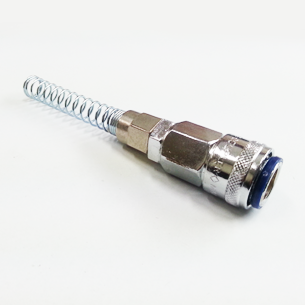
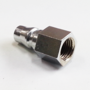
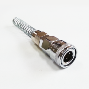
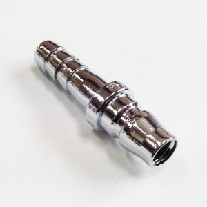
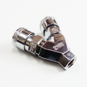
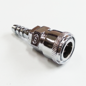
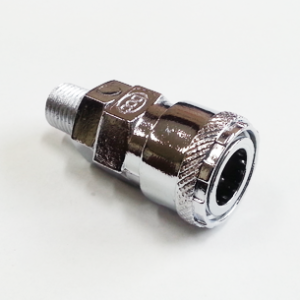
Short description: A one-way automatic pneumatic coupler with built-in poppet valve, offered in zinc-plated, steel and brass constructions. Designed for quick, smooth connection and disconnection of compressed-air lines and hoses for pneumatic tools and factory air piping.
Introduction
The PN Automatic Coupler is a one-directional quick-connect coupling engineered for efficient and safe operation in compressed-air systems. Featuring an integrated poppet valve, the PN series enables automatic opening and closing of the flow path when the mating plug is connected or disconnected—minimizing air loss, preventing contamination ingress, and improving operator safety. Offered in chrome-plated zinc die-cast (ZnDC), steel and brass constructions, the PN coupler family spans a broad set of industrial and commercial applications that require reliable, fast hose and piping connections for pneumatic tools, factory air distribution, and general-purpose fluid-handling systems.
This article provides a comprehensive technical treatment of the PN Automatic Coupler (Zinc) variant: its design and function, materials and build quality, specifications, practical use cases, comparisons with other coupler types and materials, maintenance procedures, and selection guidelines for technical professionals specifying couplers for systems and installations.
Technical Overview
Function and Operating Principle
The PN Automatic Coupler is designed as a one-way (one-directional) coupler: the internal valve (poppet) remains closed when the coupler is not mated, preventing fluid or compressed-air escape from the supply side. When a compatible plug is pushed into the coupler, a mechanical actuation pushes the poppet open, establishing flow through the coupling. On disconnection, the poppet returns to the closed position automatically, sealing the coupler and preventing residual flow. This automatic open/close mechanism provides rapid connect/disconnect functionality without the need for manual valve operation.
Key elements of the operating principle:
- Poppet valve: A spring-loaded valve element that seals the flow path when unmated and retracts when the plug pushes it, allowing flow.
- One-way flow: Flow is permitted in the intended direction only (from supply to tool), providing practical isolation and preventing backflow.
- Automatic sealing: The poppet and seat combination forms a positive seal in the unmated state, reducing air loss and contamination entry.
- Quick-connect interface: The mechanical coupling mechanism is designed for smooth engagement and disengagement with minimal insertion force and low wear.
Applications and Typical Use Cases
The PN coupler family is widely used in environments where compressed air, light oils, and water must be supplied quickly and frequently to portable tools or distribution lines. Typical applications include:
- Industrial plant compressed-air distribution networks
- Pneumatic hand tools and shop air hookups in automotive and maintenance facilities
- Assembly lines and automated workstations requiring rapid tool exchange
- General-purpose utility lines for water or low-viscosity oil services (where material compatibility permits)
- Temporary test rigs and instrumentation requiring frequent connect/disconnect cycles
Advantages of the PN One-Way Automatic Design
- Minimized air loss during disconnect (automatic closing poppet)
- Fast and repeatable connections reduce downtime
- Reduced contamination ingress into piping due to sealed unmated condition
- Simple, robust mechanical construction suitable for frequent use
- Available in multiple materials to match environment and media
Specifications and Dimensions
The tables below compile the key measurable technical attributes for the PN Automatic Coupler family. Where model-specific values are required, the table shows typical, realistic ranges for each variant and model series. All units are given in metric and imperial where applicable.
General Technical Specifications
| Parameter | Specification |
|---|---|
| Rated working pressure | 0 – 150 PSI (0 – 990 kPa) |
| Operating temperature range | 0 – 60 °C (32 – 140 °F) |
| Media compatibility | Compressed air, water, low-viscosity oil (confirm seal material compatibility for oils) |
| Valve type | Spring-loaded poppet (automatic open/close) |
| Body finishes | Chrome-plated zinc die-cast (ZnDC), plated steel, polished/exposed brass |
| Typical seal materials | NBR (nitrile) or equivalent elastomers; check material datasheet for high-temperature or chemical service |
| Compatible tubing sizes (examples) | φ5×φ8, φ6.5×φ10, φ8×φ12 polyurethane coil tubes |
Model-Level Specifications (Typical)
The following table lists typical model variants in the PN family and their representative, realistic dimension and weight data. These values are indicative and should be confirmed against the manufacturer’s datasheet for exact tolerances and dimensional drawings before procurement or CAD design.
| Model | Compatible Tube (ID × OD) | Nominal Bore (mm) | Typical Length (mm) | Typical Body Diameter (mm) | Material / Finish | Approx. Weight (g) | Rated Pressure |
|---|---|---|---|---|---|---|---|
| OSN8 | φ5 × φ8 mm | 5.0 | 30 | 16 | ZnDC (chrome-plated) | 33 | 0–150 PSI |
| SN8 | φ5 × φ8 mm | 5.0 | 34 | 16 | Steel (plated) | 38 | 0–150 PSI |
| OSN10 | φ6.5 × φ10 mm | 6.5 | 40 | 20 | ZnDC (chrome-plated) | 55 | 0–150 PSI |
| SN10 | φ6.5 × φ10 mm | 6.5 | 44 | 20 | Steel (plated) | 63 | 0–150 PSI |
| OSN12 | φ8 × φ12 mm | 8.0 | 50 | 24 | ZnDC (chrome-plated) | 85 | 0–150 PSI |
| SN12 | φ8 × φ12 mm | 8.0 | 54 | 24 | Steel (plated) | 95 | 0–150 PSI |
| PN8 | φ5 × φ8 mm | 5.0 | 32 | 16 | Brass (polished) | 40 | 0–150 PSI |
| PN10 | φ6.5 × φ10 mm | 6.5 | 45 | 20 | Brass (polished) | 72 | 0–150 PSI |
| PN12 | φ8 × φ12 mm | 8.0 | 58 | 24 | Brass (polished) | 115 | 0–150 PSI |
Notes: The “Typical Length” and “Body Diameter” fields are nominal overall dimensions representing common designs. The “Approx. Weight” values reflect typical unit weights and vary by specific design details, thread options, and finishes. Always verify final dimensions and weights from the vendor’s product drawing for mounting, routing, and CAD integration.
Materials and Build Quality
The PN automatic coupler family is designed with three primary material families to address diverse operating conditions and lifecycle expectations: ZnDC (chrome-plated zinc die-cast), steel (typically plated for corrosion resistance), and brass (polished or natural). Each material choice comes with trade-offs in strength, corrosion resistance, machinability, cost, and application suitability.
Chrome-plated Zinc Die-Cast (ZnDC)
ZnDC bodies are produced via die-casting, which provides cost-effective production with good dimensional repeatability. The coupler body is then chrome-plated to increase surface hardness, corrosion resistance and to provide an easily cleaned finish. Key attributes:
- Cost-effective for medium-duty applications
- Excellent surface finish for operator handling
- Chrome plating improves corrosion resistance versus bare zinc
- Suitable for general industrial compressed-air use
Limitations: Zinc die-cast alloys have lower tensile strength and impact resistance than steel, so ZnDC is better suited for applications without frequent heavy mechanical abuse.
Plated Steel
Steel-bodied couplers provide elevated mechanical robustness and resistance to mechanical wear and impact. Steel bodies are typically plated (e.g., nickel or zinc) to mitigate corrosion. Key attributes:
- Higher mechanical strength and wear resistance
- Better performance where impact or heavy mechanical loads are expected
- Longer fatigue life under high-duty cyclic engagement
Limitations: Steel requires plating to achieve good corrosion resistance; in aggressive or maritime environments specialized surface treatments or material selection may be required.
Brass
Brass couplers (often machined or forged) excel in corrosive or wet environments and are commonly used for compressed air, water, and certain oil applications. Brass offers excellent machinability and good sealing properties with common elastomers. Key attributes:
- Outstanding corrosion resistance in wet or chemically mild environments
- Good longevity—particularly where repeated make/break cycles are common
- Non-sparking and easy to machine for tight tolerances on sealing surfaces
Limitations: Higher material cost compared to ZnDC and steel, and reduced mechanical strength relative to hardened steel in extremely high-impact scenarios.
Poppet and Seal Materials
The internal poppet and seat are typically designed with elastomeric seals such as NBR (nitrile rubber) chosen for their compatibility with air, water and many oils. Alternate seal materials (e.g., FKM/Viton for improved chemical and temperature resistance) can be specified for specific service conditions. Proper seal selection is critical to maintain pressure rating, minimize leakage and extend service life.
Key Features
The PN Automatic Coupler family includes several design features that provide technical advantages for compressed-air systems and fluid-handling applications:
- Automatic poppet valve: Prevents flow when disconnected and opens only when properly mated, reducing air loss and enhancing safety.
- Smooth mating geometry: Engineered profiles for plug and socket reduce the insertion force and wear, enabling thousands of cycles.
- Material options: ZnDC, plated steel and brass bodies for environment-specific selection.
- Compact footprint: Low-profile designs for space-constrained installations and coiled tubing compatibility.
- Multiple tube size compatibility: Designed to work with popular polyurethane coil tube sizes (φ5×φ8, φ6.5×φ10, φ8×φ12).
- Operator ergonomics: Rounded edges and accessible sleeve features promote ease of use with gloves.
- Serviceability: Replaceable seals and internal components for cost-effective maintenance.
Use Cases / Applications
PN couplers are versatile components used by mechanical engineers, maintenance teams and system designers across numerous sectors. The following application scenarios are representative and demonstrate how to reason about selection and deployment.
1. Manufacturing and Assembly Lines
Assembly lines that require frequent tool changes or reconfiguration benefit from PN couplers’ automatic shut-off feature. When tools are disconnected, air loss is minimized and downstream drop in pressure is avoided, thus maintaining line performance and saving energy.
2. Automotive and Maintenance Shops
In workshops where pneumatic impact wrenches, ratchets and sanders are used, the PN coupler provides fast tool swaps and reduces the risk of accidental air discharge left to escape after tool removal. The zinc-plated variant offers a good balance of cost and wear resistance for general workshop environments.
3. Test Benches and Prototyping Rigs
Test rigs that require temporary connections for sensors or actuators benefit from the quick and secure mating provided by the PN coupler. The automatic valve protects equipment and instrumentation from uncontrolled discharges during reconfiguration.
4. Fluid Services (Water and Light Oils)
Provided that seals are compatible, PN couplers in brass construction can be used in water or low-viscosity oil services where corrosion resistance and long life are important. Confirm seal material compatibility with the fluid before specifying.
5. Portable and Field Equipment
Field service tools and portable pneumatic equipment benefit from the PN coupler’s compact design and automatic shut-off, enabling one-person operation and safe disconnection under field conditions.
Comparison with Similar Products
When selecting a coupler, engineers often compare material variants and coupling types. The following tables contrast the PN Automatic Coupler (Zinc) against alternative materials and against another common coupler architecture (two-way quick couplers).
Material Comparison — Zinc vs Steel vs Brass
| Attribute | Zinc (ZnDC, chrome-plated) | Plated Steel | Brass |
|---|---|---|---|
| Typical cost | Low | Medium | High |
| Corrosion resistance | Moderate (improved by plating) | Moderate (requires plating) | High |
| Mechanical strength / impact resistance | Moderate | High | Moderate |
| Suitability for wet/corrosive environments | Limited to moderate | Limited, depends on plating | Excellent |
| Typical lifecycle for high-cycle use | Good | Very good | Very good |
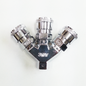
Coupler Architecture Comparison — One-Way PN Coupler vs Two-Way Quick Couplers
| Attribute | PN One-Way Automatic Coupler | Two-Way Quick Coupler |
|---|---|---|
| Flow control | Automatic shut-off on unmated side (prevents flow) | Both sides may flow or may have dual poppets (depends on design) |
| Use case | Supply-side isolation (tool connection to supply) | General-purpose quick disconnects, fluid transfer where both sides may be pressurized |
| Safety on disconnect | High—prevents supply loss when disconnected | Varies—can allow discharge unless valves present |
| Typical application | Pneumatic tools, one-direction feed lines | Hydraulic or pneumatic circuits requiring quick change of pressure-bearing lines |
Benefits and Limitations
Benefits
- Reduced air loss: The automatic poppet prevents significant air escape during disconnection—translating to energy and cost savings over time.
- Safety: Automatic isolation reduces the risk of injury from sudden tool release or uncontrolled air discharge.
- Durability: Robust metallic construction and replaceable seals support long service life under normal operating conditions.
- Ease of use: Fast, repeatable connections reduce downtime during tool swaps or reconfiguration.
- Versatility: Material options and multiple tube compatibilities make PN couplers suitable for diverse environments.
Limitations
- Temperature limit: Standard operating range (0–60 °C) can restrict use in extreme thermal environments; high-temperature variants or alternate seals may be required.
- Chemical compatibility: Seal materials may not be compatible with all oils, solvents, or aggressive chemicals—selection must be validated for the fluid in service.
- Mechanical abuse: ZnDC variants can be susceptible to mechanical damage if subjected to heavy impact or crush loads; consider steel or brass in harsh environments.
- Pressure rating: Rated to 150 PSI; high-pressure pneumatic or hydraulic systems will require alternative couplers engineered for higher pressures.
Installation, Maintenance, and Care Guide
Correct installation and ongoing maintenance are essential to achieve expected performance and service life from PN couplers. The guidance below is intended for technical personnel responsible for installation, inspection and maintenance.
Pre-Installation Checklist
- Verify the model variant and material match the intended application and media compatibility.
- Confirm operating pressure does not exceed the coupler’s rated 150 PSI (990 kPa).
- Ensure tubing or hose size matches the coupler’s compatible tube specification (φ5×φ8, φ6.5×φ10, φ8×φ12 or model-specific size).
- Inspect threaded interfaces for compatibility (if a threaded adapter is being used) and ensure proper threading standard (e.g., BSP or NPT as required by system) — consult vendor documentation.
- Prepare sealing materials for threaded connections where applicable (e.g., PTFE tape or approved thread sealant). Avoid over-application that could contaminate flow paths.
Installation Best Practices
- Mount couplers in locations that minimize mechanical strain on hoses and connectors; provide strain relief where hoses bend sharply.
- When installing threaded adapters, tighten to a firm hand-plus wrench feel—avoid over-torquing which can deform threads or damage plated finishes. If the manufacturer provides torque specifications, follow those values.
- Use FRL (Filter-Regulator-Lubricator) upstream of tools and couplers to remove particulate and condensate, regulate pressure and provide proper lubrication where required by pneumatic equipment.
- Ensure proper support and routing to prevent repeated impact or bending loads on coupler housings.
Routine Maintenance Schedule
Establishing a maintenance schedule tailored to the duty cycle is recommended. The following intervals are typical starting points; adjust frequency based on usage:
- Daily / Shift-level visual inspection: Check for signs of leakage, external damage, or loose mounting.
- Monthly: Inspect coupling function—mate and unmate several times and check for smooth operation. Inspect the sleeve and poppet for debris or wear.
- Quarterly: Remove couplers and inspect internal seals and poppet seating surfaces. Clean with suitable solvents that do not attack the seal material.
- Annually: Replace seals and elastomer components as part of preventive maintenance if couplers are in heavy use. Inspect and replace any coupling with visible corrosion or pitting on sealing surfaces.
Cleaning and Lubrication
- Clean exterior surfaces with a mild detergent and water; avoid abrasive cleaners that damage plating.
- Internal cleaning: Use compatible solvents that will not swell or degrade elastomer seals. For NBR seals, avoid ketones and certain chlorinated solvents.
- Light lubrication of moving metal parts with a silicone or pneumatic-grade lubricant may improve feel and reduce wear. Avoid over-lubrication which can attract debris.
Seal Replacement and Spare Parts
Identify and stock critical spare parts: poppets, springs and seal kits (O-rings, seat gaskets). When replacing seals, ensure parts are OEM-specified or verified compatible by material and dimensions. Document serial numbers and model variants for accurate replacement part sourcing.
Troubleshooting Common Issues
- External leakage from body threads: Check thread sealant integrity; reapply PTFE tape or approved sealant and tighten to proper torque.
- Leak at mating interface (when coupled): Inspect plug for damage, dirt or worn sealing surfaces. Clean both coupling faces and replace seals if necessary.
- Flow restriction: Check for internal debris, damaged poppet or compressed seals; disassemble and clean if permitted by the vendor’s service instructions.
- Stiff or difficult mating/unmating: Inspect for foreign material in sleeve or latch mechanism. Lubricate lightly with approved lubricant and cycle several times to redistribute lubricant.
Selection Guidelines and Engineering Considerations
When engineers specify PN couplers for new systems or retrofit projects, consider the following decision criteria:
- Duty cycle: High cycle applications (frequent connect/disconnect) favor steel or brass for superior wear life.
- Environmental conditions: Wet, corrosive or maritime environments typically favor brass due to its corrosion resistance.
- Mechanical abuse and impact: Where mechanical shock or vibration is expected, plated steel variants offer robustness.
- Elastomer compatibility: Ensure seal material selection is compatible with media (oils, solvents) and temperatures expected in service.
- Pressure and flow requirements: Validate that the coupler’s internal bore and poppet geometry can deliver the required flow without excessive pressure drop; for high-flow requirements, choose larger-bore models (e.g., PN12).
- Space constraints: Compact ZnDC units may be preferred for tight routing, though trade-offs in strength must be considered.
Safety Considerations
PN couplers significantly improve safety through automatic isolation, but safe use requires observance of established compressed-air handling procedures:
- Always depressurize lines, shut off supply and bleed residual pressure before disassembling any coupler or hose connection.
- Do not couple or uncouple under full load unless the coupler is designed for hot-mate or under-pressure operation and the manufacturer’s instructions permit such actions.
- Wear appropriate personal protective equipment (PPE) such as eye protection and gloves when connecting or disconnecting pressurized lines.
- Use couplers with rated pressure margins—do not exceed the 150 PSI rating on standard PN models.
Practical Design Examples
The following short design scenarios illustrate practical selection and layout considerations.
Example A — Shop Air Distribution Drop for Multiple Tools
Scenario: A maintenance bay with three workstations requires quick disconnects for impact wrenches and air ratchets. Each station uses coiled 8 mm OD polyurethane tubing connected to drop points.
- Recommended coupler: PN10 or OSN10 (compatible with φ6.5×φ10 tubing) to balance flow and compactness.
- Material: ZnDC (chrome-plated) provides acceptable durability for indoor shop environment at competitive cost.
- Installation notes: Install FRL at the supply manifold and place couplers at ergonomic height with strain relief for coiled hose.
Example B — Corrosive Environmental Application
Scenario: An assembly workstation in a humid coastal plant experiences significant corrosion on exposed fittings.
- Recommended coupler: Brass PN series (PN12 for higher flow demands) due to superior corrosion resistance.
- Seal selection: Use NBR for general pneumatic service; if oil or higher temperatures are present, consider FKM seals after compatibility verification.
- Installation notes: Use corrosion-resistant clamps and supports; schedule more frequent inspections in saline environments.
Procurement and Quality Assurance Tips
- Request data sheets with dimensional drawings, maximum flow data, Cv values (if available) and full material declarations.
- Confirm supply chain traceability and batch identification to track quality and perform recalls if necessary.
- Insist on test-reported performance if couplers will be part of safety-critical installations (e.g., leak testing at rated pressure prior to commissioning).
- Consider requesting sample units for qualification testing—subject them to the anticipated duty cycles and media exposures.
Conclusion
The PN Automatic Coupler (Zinc) is a compact, economical and practical quick-connect solution for one-way pneumatic connections in industrial and commercial compressed-air systems. With its spring-loaded poppet valve, automatic sealing upon disconnection, and compatibility with common polyurethane tubing sizes, the PN family supports efficient operations, reduced air loss and enhanced safety. The availability of ZnDC (chrome-plated), plated steel and brass variants enables specification across varied environmental and mechanical conditions.
For technical professionals, selection of the correct PN coupler variant should be based on duty cycle, media compatibility, environment, and flow requirements. Proper installation, routine inspection, and proactive maintenance are critical to preserving performance, minimizing downtime and extending product life. When properly specified and maintained, PN Automatic Couplers deliver robust, repeatable connections that support productive pneumatic systems in factories, workshops and field operations.
If you require model-specific CAD drawings, detailed flow (Cv) data, or material certificates for compliance and procurement, consult the manufacturer’s technical documentation or request certified test reports to support engineering qualification.
Appendix — Quick Reference Conversions
- 150 PSI = 990 kPa (rounded)
- Temperature range 0–60 °C = 32–140 °F
- Common tube sizes referenced: φ5×φ8 (ID 5 mm), φ6.5×φ10 (ID 6.5 mm), φ8×φ12 (ID 8 mm)
For additional technical questions, assistance with system integration, or help selecting the optimal PN coupler variant for a specific application, contact your supplier’s technical support or an experienced pneumatic systems engineer.

Reviews
There are no reviews yet.