
 Tiếng Việt
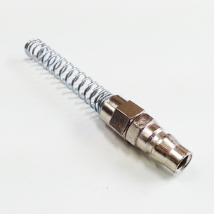
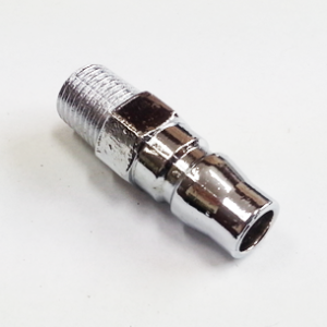
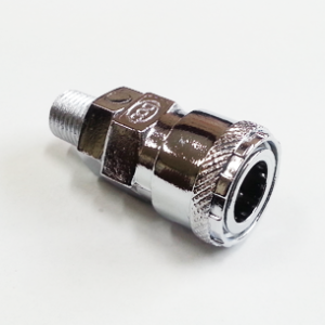
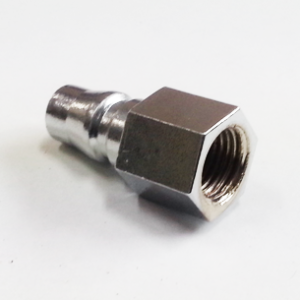
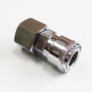
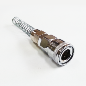
PN Coupler ZINC — Zinc Quick-Connect Coupler for Compressed-Air Systems
The PN Coupler ZINC is a purpose-built zinc quick-connect coupler designed for compressed-air piping, hose connections and air-powered tool interfaces in industrial and workshop environments. Engineered with a built-in one-way automatic shut-off valve, it provides rapid, safe and low-loss connections between supply lines and pneumatic tools or branch hoses. This article delivers a comprehensive technical review of the PN Coupler ZINC: its design, specifications, materials, installation and maintenance best practices, comparative analysis with alternative coupler materials, and guidance for selecting the correct model for your application.
Introduction
Quick-connect couplers are fundamental components in modern industrial compressed-air systems. They reduce downtime during tool changes, simplify hose routing, and mitigate inadvertent air loss when equipment is disconnected. The PN Coupler ZINC combines ease-of-use with rugged zinc construction and an integrated, one-way automatic shut-off valve that closes on disconnect, minimizing system depressurization and improving operational safety.
This article is aimed at engineering, maintenance and technical procurement professionals looking for a detailed, practical and technical resource to evaluate and integrate the PN Coupler ZINC into industrial compressed-air infrastructures. Coverage includes technical specification tables, dimensional data, material analysis, performance characteristics, installation and maintenance procedures, and a comparison to alternative coupler choices such as brass, stainless steel and polymer composite couplers.
Technical Overview
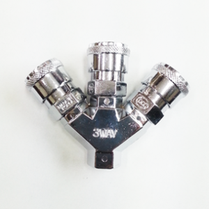
At its core, the PN Coupler ZINC is a quick-disconnect fitting that provides a secure, low-leakage connection between a supply line and a mating plug. The coupler houses a spring-loaded poppet (one-way automatic shut-off valve) that seals the supply side when the mating plug is removed. This automatic shut-off limits air loss during tool swaps and prevents backflow in multi-branch distribution manifolds.
Primary functions
- Enable rapid connect/disconnect of pneumatic hoses and tools.
- Automatically shut off and seal the supply when disconnected to limit air loss.
- Provide a reliable, repeatable mechanical seal for compressed air, water and oil services within the specified operating parameters.
- Accommodate multiple tube/hose sizes and installation requirements via a family of models (PN8, PN10, PN12, OSN/SN variants).
Operating envelope
Key operating parameters for PN Coupler ZINC (typical range):
- Working pressure: 0–150 psi (0–9.9 kgf/cm²; 0–990 kPa).
- Working temperature: 32–140 °F (0–60 °C).
- Compatible media: compressed air, water and mineral oil—compatibility depends on seal material selection.
- Valve type: internal one-way automatic shut-off (spring-loaded poppet).
Note: Seal material selection (e.g., NBR/nitrile, EPDM, FKM/Viton) affects chemical compatibility and temperature limits. Confirm seal material when sourcing for non-standard fluids or higher temperatures.
Specifications and Dimensions
Below are the technical specifications and dimensional references for the PN Coupler ZINC family. The tables present general product specifications followed by per-model dimensional and mass data. Values labeled “approximate” are meant to provide guidance for layout and selection; always verify precise dimensions with supplier datasheets prior to fabrication or panel design.
General technical specifications
| Parameter | Value (typical) |
|---|---|
| Body material | Zinc alloy (die-cast zinc or zinc die plate) |
| Seal material (standard) | NBR (nitrile) — alternative seals available: EPDM, FKM/Viton |
| Working pressure | 0–150 psi (0–9.9 kgf/cm²; 0–990 kPa) |
| Working temperature | 32–140 °F (0–60 °C) depending on seals |
| Compatible media | Air, water, oil (verify seal compatibility for oil types and fluids) |
| Valve | One-way automatic shut-off (spring-loaded poppet) |
| Typical plating / finish | Nickel or chrome plating for corrosion resistance (varies by supplier) |
| Standards & certifications | Industry-specific compliance varies; consult supplier for RoHS/REACH, pressure equipment conformity, and customer specifications |
Model dimensional and mass data (reference)
The PN Coupler ZINC comes in several nominal sizes and model variants to match tube/hose outer diameters and intended use. The following table summarizes model identifiers, nominal tube/hose sizes (φ indicated), approximate bore diameters, overall length, and mass. Dimensions are approximate; for integration design use the manufacturer’s detailed mechanical drawing.
| Model | Tube / Hose Size (φ) | Approx. Internal Bore (mm) | Overall Length (mm, approx.) | Weight (g) | Typical Application |
|---|---|---|---|---|---|
| PN8 | φ5 × φ8 | 3.5 | 28 | 33 | Light pneumatic hoses, small air tools |
| PN10 | φ6.5 × φ10 | 5.0 | 34 | 43 | General workshop tools, mid-size hoses |
| PN12 | φ8 × φ12 | 6.5 | 40 | 52 | Higher flow tools and manifolds |
| SN8 | φ5 × φ8 | 3.5 | 34 | 95 | Female threaded variant / reinforced body |
| OSN8 | φ5 × φ8 | 3.5 | 36 | 102 | Overmolded / reinforced coupling for higher durability |
| SN10 | φ6.5 × φ10 | 5.0 | 40 | 103 | Standard duty with threaded or reinforced body |
| OSN10 | φ6.5 × φ10 | 5.0 | 42 | 110 | Overmolded / robust body for heavy use |
| SN12 | φ8 × φ12 | 6.5 | 46 | 107 | Large-bore coupler for higher flow |
| OSN12 | φ8 × φ12 | 6.5 | 48 | 115 | Reinforced large-bore coupler |
Notes on the table: The φ notation denotes nominal tube/hose diameters used with the model. “PN” models are compact couplers with lower mass; “SN/OSN” variants indicate body modifications or over-molded options for robustness and higher mechanical resistance. Contact the supplier for CAD drawings and exact dimensional tolerances before committing to panel cutouts or manifold designs.
Materials and Build Quality
Material selection is central to the coupler’s performance and lifecycle. The PN Coupler ZINC uses a zinc alloy body, chosen for a balance of mechanical strength, cost-efficiency and machinability. Zinc alloys used in fasteners and small fittings are often die-cast zinc or zinc-aluminium alloys (e.g., Zamak family), which provide good dimensional stability and surface finish for plating.
Zinc alloy body — benefits and technical implications
- Cost-effective manufacturing: Zinc alloys are lower cost relative to brass and stainless steel, making the coupler attractive for high-volume installations.
- Good machinability and surface finish: Zinc offers excellent die-cast detail, enabling tight dimensional control for the valve components and secure sealing interfaces.
- Weight advantage: Compared to brass and stainless steel, zinc is lighter, reducing inertia on rotating assemblies and shipping weight for large installations.
- Corrosion considerations: Zinc offers moderate corrosion resistance; however, protective plating (nickel or chrome) or passivation is common. For harsh outdoor or corrosive chemical environments, consider stainless steel alternatives.
Seals and springs
The one-way shut-off valve relies on elastomeric seals and a spring to provide a leak-tight, repeatable closure. Typical choices and considerations:
- NBR (nitrile): Standard, well-suited for compressed air, general oils and moderate temperatures. Economical with good abrasion resistance.
- EPDM: Better for water service and some polar chemicals; not recommended for hydrocarbon oils.
- FKM (Viton): Higher chemical and temperature resistance, recommended for elevated temperatures or aggressive oils; higher cost.
- Spring: Stainless steel (commonly 302/304) to resist corrosion and preserve spring constant across expected cycle life.
Surface treatment
To enhance corrosion resistance and longevity, PN Coupler ZINC bodies are commonly surface-treated with plating such as nickel or chrome. Plating reduces surface oxidation, improves wear resistance and provides an attractive finish. Ensure plating adhesion quality and thickness meet the installation’s environmental exposure expectations (salt fog, humidity, chemical exposure).
Key Features
The PN Coupler ZINC incorporates a set of features that combine to deliver practical value in multiple industrial contexts:
- Built-in one-way automatic shut-off valve: Automatically closes on disconnection to minimize air loss and reduce risk of backflow.
- Multiple size models: PN8/10/12 and SN/OSN variants to suit different hose/tube diameters and duty cycles.
- Zinc construction: A balanced choice between cost, strength and weight for standard industrial use.
- Compatibility with air, water and oil: With appropriate seal choices, the coupler can serve multiple media classes.
- Smooth coupling action: Precision internal profiles ensure reliable connection and reduced operator fatigue during frequent connections.
- Low headloss: Appropriately sized internal bores in PN10/PN12 variants support higher flow rates for more demanding pneumatic tools.
- Quick replacement and maintenance: Modular internal components (poppet, seals, spring) simplify maintenance and spare parts management.
Use Cases and Applications
The PN Coupler ZINC is well-suited for a broad set of industrial and workshop applications. Typical application domains include:
Industrial plant compressed-air distribution
Localized distribution manifolds and piping networks benefit from quick-connect couplers to provide tool outlets on workstations. The automatic shut-off minimizes pressure loss when branches are disconnected during maintenance or tool swaps, improving energy efficiency and safety.
Assembly lines and manufacturing
Manufacturing cells that use pneumatic fastening tools, blow-off nozzles, and air-driven actuators frequently change tools or reconfigure stations. PN Coupler ZINC variants provide reliable, repetitive connections with little operator effort.
Maintenance, repair and operations (MRO)
MRO technicians use a variety of portable pneumatic tools. Lightweight PN models (PN8/PN10) reduce the coupling weight attached to hoses and tools, improving ergonomics during repetitive work.
Automotive repair shops
Automotive shops use hoists, impact wrenches and air ratchets. The PN12 size and SN/OSN reinforced variants support the higher flow demands of heavy-duty tools used in these contexts.
Water and light oil handling
With compatible seals (e.g., EPDM for water, FKM for oils), PN Coupler ZINC can service low-pressure water lines and lubricating oil lines in controlled environments. Ensure fluid compatibility and temperature rating before use.
Comparison With Alternative Couplers
Selecting a coupler material and family is a trade-off between cost, corrosion resistance, weight and mechanical durability. The table below presents a direct comparison of PN Coupler ZINC with common alternatives: brass couplers, stainless steel couplers, and polymer/composite couplers.
| Characteristic | PN Coupler ZINC | Brass Coupler | Stainless Steel Coupler | Polymer / Composite Coupler |
|---|---|---|---|---|
| Corrosion resistance | Moderate (improved with plating) | Good (suitable for many environments) | Excellent (best for corrosive environments) | Good to excellent (depending on polymer grade) |
| Mechanical strength | Good for general duty | High | Very high | Moderate (impacted by temperature & UV) |
| Weight | Light | Medium | High | Very light |
| Cost | Low to moderate | Moderate | High | Low to moderate |
| Temperature capability | Moderate (limited by seal selection) | Moderate-high | High | Limited (depends on polymer) |
| Suitability for water/oil/air | Suitable (with correct seals) | Suitable (commonly used) | Suitable for aggressive fluids | Suitable for dry air, light water; some polymers handle oils |
| Typical applications | General industrial, workshops | Dental, instrumentation, shop air | Marine, chemical, food (with correct seals) | Portable tools, corrosive environments with limited pressure |
In summary, PN Coupler ZINC offers a cost-effective compromise for standard industrial environments requiring reasonable corrosion resistance and repeatable performance. For highly corrosive outdoor or chemical exposure environments, stainless steel is often recommended despite the higher cost.
Benefits and Limitations
Benefits
- Cost-effective: Zinc body provides a lower-cost option versus brass and stainless steel while maintaining adequate mechanical properties for many industrial settings.
- Integrated automatic shut-off: Minimizes air loss and maintains localized pressure isolation when disconnected.
- Multiple size options: Models cover a range of hose diameters and flow requirements.
- Easy serviceability: Replaceable seals and springs reduce lifecycle costs versus disposable fittings.
- Lightweight: Reduces handling fatigue and shipping costs for large deployments.
Limitations
- Moderate corrosion resistance: Zinc is not as corrosion-resistant as stainless steel; plating helps but may not suffice in aggressive environments.
- Temperature limitations: The working temperature range (32–140 °F / 0–60 °C) is adequate for many applications but may be restrictive for high-temperature processes. Seal selection affects limits.
- Not suitable for all chemicals: Compatibility with aggressive chemicals or solvents requires careful selection of sealing compounds or alternative materials.
- Flow limitations: Smaller PN8/PN10 variants have limited flow rates for high-demand pneumatic equipment; choose PN12 or higher-flow options where necessary.
Selection Guide — Choosing the Right PN Coupler ZINC Model
Selecting the correct coupler requires consideration of fluid, pressure, flow requirements, environmental exposure, and mechanical duty cycle. Use the following checklist to guide selection:
- Determine operating pressure and temperature: Confirm peak and working pressures; ensure the coupler’s 150 psi rating and temperature limits match or exceed system conditions with margin.
- Identify media: Air, water or oil—specify the exact fluid chemistry if non-standard to select compatible seals (NBR, EPDM, FKM).
- Match hose / tube diameter: Choose the model that corresponds to the hose O.D. and nominal bore to minimize pressure drop.
- Evaluate flow demand: For high-consumption tools (e.g., grinders, impact wrenches), select PN12 or SN/OSN reinforced models to maintain acceptable pressure at the tool.
- Consider environmental exposure: For outdoor, marine or chemical environments, consider additional plating or a stainless steel alternative.
- Review mechanical duty: If the coupler will be connected/disconnected thousands of times per day, prefer reinforced SN/OSN variants and maintain a spare-part stock (seals, springs).
- Check connection type: Confirm whether you need a hose tail, push-fit, threaded male/female or panel-mount version and order matching plug/mating components.
Installation and Maintenance Guide
Proper installation and routine maintenance extend service life, reduce leaks and preserve flow capacity. The guidance below is tailored for technical personnel performing system integration or maintenance.
Installation steps
- Verify components: Inspect coupler body, mating plug and seals for damage, burrs or foreign material. Confirm part numbers and seal materials.
- Prepare hose/fitting ends: Cut hose squarely, remove any swarf, and ensure tube fittings or hose barbs match the coupler model size. For threaded connections, clean threads and use an appropriate thread sealant (PTFE tape or liquid sealant compatible with the intended fluid).
- Install seal and spring correctly: If the coupler is supplied as a serviceable or unassembled unit, install the internal poppet, spring and seal per manufacturer orientation. A misoriented poppet will prevent sealing or make connection impossible.
- Torque and fastening: Tighten threaded interfaces to the manufacturer’s recommended torque. If such data is not available, use conservative torque settings and validate for leak-free operation under pressure.
- Functional test: Pressurize the system to working pressure and observe the coupler for leaks, smooth actuation and proper shut-off on uncoupling. Repeat connect/disconnect cycles to verify smooth operation.
- Labeling and identification: For complex manifolds, label couplers with service media and maximum pressure to prevent cross-connection errors in mixed-media systems.
Preventive maintenance schedule (recommended)
- Daily: Visual inspection for external damage, leaks or excessive wear in high-use installations.
- Weekly: Functional check—connect/disconnect a few times and ensure smooth valve action and no audible leaks.
- Monthly: Inspect seals visually where accessible for cracking, extrusion or deformation; replace if signs of wear appear.
- Quarterly (or after a set number of cycles): Disassemble and clean internal surfaces, remove particulate ingress, and lubricate seals with a compatible silicone or PTFE-based grease (avoid petroleum-based greases if the seals are EPDM).
- Annually: Replace seals and springs in high-cycle environments as a planned maintenance item to prevent unplanned downtime.
Cleaning and lubrication
Use cleaning agents compatible with the chosen seal material. For NBR seals, avoid prolonged exposure to strong ketones or chlorinated solvents. Light lubrication with silicone-compatible grease reduces friction and wear on seals and aids in assembly. Do not use petroleum oils for EPDM seals as they will cause swelling and premature failure.
Troubleshooting
Common symptoms, probable causes and corrective actions are summarized below:
| Symptom | Likely cause | Corrective action |
|---|---|---|
| Air leakage when coupler is disconnected | Damaged or hardened seal, broken spring, foreign debris preventing poppet seating | Depressurize, disassemble, inspect and replace seals or springs; clean seating surfaces |
| Difficulty connecting or disconnecting | Debris on external mating surfaces, damaged latch, improper lubrication | Clean mating parts, inspect engagement features, apply light silicone grease on seals |
| Low pressure or pressure drop at tool | Coupler undersized for flow demand, internal partial blockage, excessive system piping losses | Measure inlet/outlet pressure; upgrade to larger bore model or remove blockage |
| Corrosion or pitting on body | Environment exposure (sea spray, chemical atmosphere), compromised plating | Replace corroded couplers; switch to stainless steel or enhanced plated variant in future installations |
| Seal extrusion or rapid seal wear | Excessive pressure spikes, incompatible fluids, improper seal material | Confirm seal compatibility and install appropriate pressure-limiting or mitigation devices |
Performance Considerations and Pressure Drop
The internal bore and profile determine the coupler’s flow capacity and associated pressure losses. The following notes provide a technical perspective for systems engineers considering pressure drop and flow:
- For incompressible liquids, the flow through a fitting can be approximated using the Cv (flow coefficient) relationship: Q = Cv × sqrt(ΔP / SG), where Q is flow (US gpm), ΔP is pressure drop (psi), and SG is specific gravity.
- For compressed air (a compressible fluid), use standard pneumatic flow equations (ISO 6358) or manufacturer-supplied Cv equivalents, and account for temperature and inlet pressure when estimating flow.
- Smaller PN8 couplers are intended for low to moderate flows and will incur higher pressure drop when used with high-demand tools. PN10 and PN12 offer progressively larger bores and reduced headloss.
Example — approximate Cv and flow guidance
The following approximate Cv values are provided for engineering estimates (determine exact values from supplier or by measurement):
- PN8 (approx. bore 3.5 mm) — Cv ≈ 0.03–0.05
- PN10 (approx. bore 5.0 mm) — Cv ≈ 0.06–0.10
- PN12 (approx. bore 6.5 mm) — Cv ≈ 0.10–0.20
Example calculation (liquid/approximate): For PN10 with Cv = 0.08, the expected water flow at a 1 psi pressure drop is:
Q = 0.08 × sqrt(1 / 1) = 0.08 US gpm ≈ 0.3 L/min (approximate)
This simple example highlights that small couplers produce limited flow for liquids; for compressible flows like air the volumetric flow at a given pressure drop will be significantly higher, but compressibility effects and upstream pressure loss must be accounted for using dedicated pneumatic flow analysis.
Safety Considerations
- Depressurize prior to disassembly: Always isolate and depressurize the circuit before disconnecting or servicing couplers to avoid injuries from whip or flying components.
- PPE: Use eye protection and gloves when servicing couplers; compressed air can eject particulates when fittings are disconnected under pressure.
- Secure hoses: Ensure hoses are clamped or restrained to prevent whip in the event of sudden disconnect or failure.
- Media identification: Never connect a coupler used for one medium (e.g., oil) to a line containing another (e.g., breathing air) without thorough cleaning and verification of compatibility.
- Temperature and pressure rating: Do not exceed specified working pressure and temperature limits. Pressure spikes above rating can deform internal components and cause failure.
Procurement and Spare Parts Recommendations
To minimize downtime and ensure consistent performance, plan spare parts inventory and procurement strategy:
- Keep spare seal kits (NBR/EPDM/FKM) for each coupler model in use, sized to expected replacement intervals.
- Stock replacement springs and poppet assemblies for high-cycle applications.
- Purchase matching mating plugs and test kits to verify coupler performance after maintenance.
- When ordering, specify body material, seal material, finish/plating, hose/tube size and connection type to avoid cross-compatibility issues.
Examples of Typical Specification Language for Purchase Orders
When specifying PN Coupler ZINC for procurement, include the following information to avoid ambiguity:
- Part number / model (e.g., PN10, OSN12)
- Body material: Zinc alloy; finish: nickel-plated
- Seal material: NBR (or EPDM / FKM as required)
- Working pressure: up to 150 psi
- Operating temperature: 0–60 °C (32–140 °F)
- Connection type: hose barb / push-fit / male/female thread — specify thread standard (BSPP, NPT, metric) if applicable
- Quantity, packaging and delivery lead time
Case Study — Implementing PN Coupler ZINC in a Manufacturing Cell
A mid-sized manufacturing cell automated a pneumatic fastening station. The system previously utilized fixed hoses and manual valve isolation, leading to substantial downtime during tool maintenance. The engineering team retrofitted the stations with PN Coupler ZINC PN10 outlets at each workstation and supplied matching plugs on portable tool hoses.
Outcomes observed after six months:
- Tool changeover time decreased by 70% due to fast connect/disconnect.
- Air loss during tool swaps was reduced by approximately 85% because of the automatic shut-off valve in each coupler.
- Maintenance reported fewer leaks compared to prior inexpensive couplers thanks to better sealing profiles and planned seal replacement intervals.
Lessons learned: For high-cycle stations, switching to OSN reinforced models minimized body wear at interconnection points and improved lifetime before replacement.
Conclusion
The PN Coupler ZINC is a pragmatic choice for compressed-air distribution and hose connections where cost-efficiency, light weight and reliable automatic shut-off are required. With multiple sizes (PN8, PN10, PN12) and reinforced SN/OSN variants, it addresses a range of flow and durability needs in workshops, production lines, MRO shops and automotive facilities. Material selection, seal compatibility and environmental exposure should be part of the procurement and selection process to ensure long-term reliability.
For systems requiring enhanced corrosion resistance, higher temperature performance, or aggressive chemical compatibility, consider stainless steel or alternative seal materials. For standard plant air and general-purpose fluid handling, PN Coupler ZINC provides an effective balance of performance and economy.
For detailed CAD models, specific Cv values, or certification documentation, consult the PN Coupler ZINC manufacturer or authorized distributor and request the product datasheet and dimensional drawings before final selection and installation.
Appendix — Quick Reference
- Working pressure: 0–150 psi (0–9.9 kgf/cm²; 0–990 kPa)
- Temperature range: 32–140 °F (0–60 °C), dependent on seals
- Materials: Zinc body; standard seals NBR (alternatives EPDM/FKM)
- Model examples: PN8 (φ5 × φ8, 33 g), PN10 (φ6.5 × φ10, 43 g), PN12 (φ8 × φ12, 52 g), SN/OSN variants for reinforced bodies
- Applications: Compressed air, low-pressure water and oil service (verify seals)
If you would like, I can generate a printable one-page datasheet or CAD-ready drawing checklist for procurement and installation teams based on your selected PN Coupler ZINC model and application parameters—tell me the model and operating conditions and I will prepare it.

Reviews
There are no reviews yet.