
 Tiếng Việt
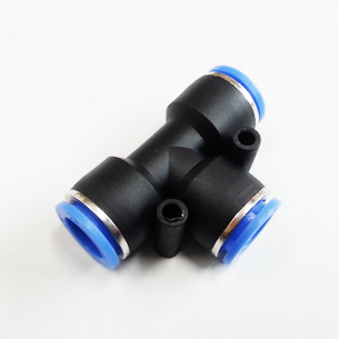
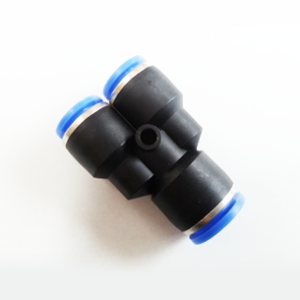
PUT Union Tee — One-Touch Pneumatic Union Tee for Rapid, Tool-Free Tube Connections
PUT Union Tee is a one-touch pneumatic union tee designed to provide fast, reliable, and service-friendly distribution and branch connections in compressed air systems. Engineered for push-to-connect tube installation and quick tool-free disconnection, the PUT Union Tee supports commonly used metric and inch tube sizes, offers robust sealing with thread-seal coating, and is optimized for compact assemblies and rapid maintenance cycles. This article delivers a comprehensive technical overview, real-world use cases, performance data, installation and maintenance guidance, and a balanced comparison with alternative fittings.
Introduction
In modern pneumatic systems, minimizing downtime and simplifying maintenance while maintaining leak-tight performance is critical. The PUT Union Tee addresses those demands by combining one-touch push-in convenience with a compact tee architecture for branching air lines. The product is intended specifically for compressed air applications and is suitable for distribution manifolds, local branch lines, and modular assemblies where quick reconfiguration may be required.
This article provides an in-depth technical profile of the PUT Union Tee, including operating limits, compatibility, materials and build-quality considerations, detailed specifications, installation best practices, maintenance guidance, and comparative analysis against other common tee fittings used in industry.
Technical Overview
The PUT Union Tee is a push-in (one-touch) union tee fitting that allows a tube to be pushed into the fitting until a positive engagement is achieved and sealed. Removal is equally rapid: depress the release sleeve and withdraw the tube in 1–2 seconds. The fitting is optimized for compressed air only and is rated for pressures, vacuum, and temperature ranges typical of industrial and automation environments.
Key technical aspects:
- Connection method: Push-in (one-touch) for quick tool-free insertion and removal.
- Intended fluid: Compressed air only—do not use with liquids, aggressive gases, or oxygen systems.
- Pressure range: 0–150 PSI (0–9.9 kgf/cm² / 0–990 kPa).
- Vacuum rating: Down to -29.5 in Hg (-750 mm Hg / ~10 Torr).
- Temperature range: 0–60°C (32–140°F).
- Tube compatibility: Metric: 4, 6, 8, 10, 12, 16 mm. Inch: 5/32″, 3/16″, 1/4″, 5/16″, 3/8″, 1/2″.
- Seal and thread treatment: Threaded portions are seal-coated to simplify installation and reduce need for additional tape or compound.
- Body form factor: PC-type body with internal and external hex flats for ease of assembly in confined spaces.
Mechanically, the fitting employs a retention collet (grip ring) that holds the tube, an elastomer O‑ring or lip seal to provide a pressure-retaining seal, and a sleeve that actuates the collet release. These elements are dimensioned to ensure secure engagement over the operating pressure range while allowing rapid disassembly for line changes or service.
Specifications and Dimensions
The following tables summarize the primary dimensional and performance data for the PUT Union Tee family. Data is given per nominal tube size; specific part numbers follow the format MODEL (φD-T), for example PUT 04 (metric) corresponds to PUT 5/32 (inch) in the inch series.
Operating & Performance Specifications
| Parameter | Value |
|---|---|
| Intended fluid | Compressed air only |
| Operating pressure | 0 – 150 PSI (0 – 9.9 kgf/cm² / 0 – 990 kPa) |
| Maximum vacuum | Down to -29.5 in Hg (-750 mm Hg / ~10 Torr) |
| Operating temperature | 0 – 60°C (32 – 140°F) |
| Media temperature limits | Same as operating temperature; avoid direct exposure to hot surfaces or UV for extended periods |
| Material class (typical) | Engineered thermoplastic body, elastomeric seals, stainless/steel reinforcement for collet (see Materials section) |
| Installation | Push-in / one-touch; release sleeve for disassembly |
Dimensional and Flow Table by Nominal Tube Size
Note: The following dimensions and flow values are representative for the PUT Union Tee geometric family. Exact dimensions for a given part number may vary slightly between metric and inch-coded variants. Mass values are approximate.
| Nominal Tube Size | Model Code (example) | Approx. A (Body Width) | Approx. B (Overall Length) | Approx. C (Height) | Internal Flow Dia. (mm) | Approx. Max Flow (L/min, free flow) | Approx. Weight (g) | Thread Options |
|---|---|---|---|---|---|---|---|---|
| Metric 4 mm / Inch 5/32″ | PUT 04 / PUT 5/32 | 18 mm | 26 mm | 20 mm | 3.0 | 50 – 80 L/min | 8 – 12 g | G1/8, 1/8″ NPT, BSPP (selected) |
| Metric 6 mm / Inch 3/16″ | PUT 06 / PUT 3/16 | 20 mm | 30 mm | 22 mm | 4.0 | 90 – 130 L/min | 12 – 18 g | G1/8, 1/8″ NPT, BSPP |
| Metric 8 mm / Inch 1/4″ | PUT 08 / PUT 1/4 | 24 mm | 34 mm | 26 mm | 5.0 | 150 – 220 L/min | 18 – 28 g | G1/8, 1/8″ NPT, 1/4″ BSPP/NPT |
| Metric 10 mm / Inch 5/16″ | PUT 10 / PUT 5/16 | 30 mm | 40 mm | 30 mm | 6.2 | 250 – 320 L/min | 28 – 40 g | 1/4″ BSPP/NPT, 3/8″ options |
| Metric 12 mm / Inch 3/8″ | PUT 12 / PUT 3/8 | 36 mm | 48 mm | 34 mm | 7.2 | 350 – 430 L/min | 40 – 55 g | 1/4″–3/8″ BSPP/NPT |
| Metric 16 mm / Inch 1/2″ | PUT 16 / PUT 1/2 | 44 mm | 56 mm | 40 mm | 9.0 | 500 – 700 L/min | 60 – 85 g | 3/8″–1/2″ BSPP/NPT |
Notes on the dimensional table: “A”, “B”, and “C” represent nominal envelope dimensions for planning and installation; confirm exact dimensions from manufacturer drawings for tight-fit applications. Flow values are representative “free flow” capacities for compressed air at nominal system pressures; actual flow in application will depend on system pressure, tubing length, number of fittings, and other restrictions.
Materials and Build Quality
Understanding the materials and how they influence durability, compatibility, and performance is critical when specifying pneumatic fittings.
Typical Component Materials
- Body: Engineered thermoplastic such as polyamide (PA), polybutylene terephthalate (PBT), or polycarbonate (PC) grade. These polymers are chosen for impact resistance, dimensional stability, and resistance to typical workshop contaminants. The long description refers to a “PC-type body,” which denotes the body architecture (push-fit connector style) and commonly indicates a high-performance thermoplastic housing.
- Collet (retention ring): Often stainless steel or plated spring steel with plastic overmold, providing mechanical retention for the tube. Stainless components are preferred in corrosive or washdown environments.
- Release sleeve: High-wear thermoplastic or polymer composite designed for repeated actuations without cracking.
- Seals: Elastomeric seals such as NBR (nitrile) or FKM (fluoroelastomer) depending on temperature and contamination tolerance. NBR is common for compressed air systems; FKM may be used in higher temperature or chemically aggressive conditions (confirm compatibility for any oil-laden or specialty gases).
- Thread seal coating: A PTFE-based or polymeric seal coating is typically applied to threaded metal inserts or metal thread forms. This reduces the need for separate tapes or sealants and also reduces the risk of foreign particulate contamination from loose tape.
- Threaded inserts / metal components: Where metal threads are required (to meet mechanical strength or standardized thread dimensions), corrosion-resistant metals such as brass, nickel-plated brass, or stainless steel are commonly used.
Build Quality Considerations
When evaluating the PUT Union Tee for a system, consider:
- Tolerance control: Accurate molding tolerances and consistent collet geometry ensure reliable retention forces across batches and tube types.
- Seal hardness and dynamic performance: O-ring hardness must balance low friction for insertion with sufficient compression resistance to maintain seal under pressure cycling.
- Wear properties: Release sleeve and collet surfaces must resist abrasion from repeated insertions and tube materials (especially PTFE-coated or grooved tubing).
- Thread quality and coating adhesion: Proper adhesion of thread seal coating ensures that the coated threads provide predictable torque and sealing characteristics during installation.
- Compatibility validation: Manufacturers typically test fittings for cycle life, pressure cycling, and leak performance. Request cycle-life data for demanding installations (e.g., frequent reconfiguration demands).
Key Features
The PUT Union Tee includes a range of features designed to support industrial pneumatic installations. Below are the primary features and technical benefits.
- One-touch push-in connection: Enables rapid insertion of tubing without tools—saves install time and reduces reliance on skilled technicians for line changes.
- Tool-free disconnection: Tubes can be removed in 1–2 seconds by depressing the sleeve—convenient for reconfiguration and maintenance.
- Wide size coverage: Supports common metric and inch tube sizes across small to moderate bore ranges (4–16 mm and 5/32″–1/2″).
- Compact PC-type body: Small footprint with internal/external hex flats for tightening in confined areas and for use with standard wrenches when threaded engagement is required.
- Seal-coated threads: Simplifies installation and reduces risk of loose tape contamination—ideal for assembly-line installations and field maintenance.
- High vacuum compatibility: Rated to near-full vacuum (down to -29.5 in Hg), allowing use in applications with partial evacuations or negative-pressure states.
- Robust operating envelope: Up to 150 PSI and temperatures up to 60°C, covering the vast majority of industrial compressed-air systems.
- Interchangeable sizing coding: Clear model coding that maps metric and inch sizes for easier BOM management across mixed installations.
Use Cases and Applications
The PUT Union Tee is broadly applicable across industries and machine classes that use compressed air for actuation, control, or pneumatic transport. Below are specific use cases and the reasons PUT Union Tee is suitable in each.
1. Machine Tooling and Automation
Pneumatic manifolds and local branch lines feeding cylinders and grippers require compact tees to split supply lines. The PUT Union Tee is ideal because of:
- Rapid maintenance (tool-free disconnection) for line changes during production swaps.
- Compact geometry for tight spaces at valve islands and actuator clusters.
- Sufficient pressure rating for typical pneumatic actuation circuits.
2. Packaging and Assembly Lines
Packaging machines frequently require modular changeover. The PUT Union Tee enables:
- Quick reconfiguration during product changeovers.
- Minimized downtime due to tool-free disconnection.
- Reliable sealing to reduce product contamination risk from leaks.
3. Laboratory Gas Distribution (Non-reactive Gases)
For non-reactive compressed air distribution in test stands and laboratory benches, the vacuum capability and precise sealing of the PUT Union Tee make it useful where temporary lines are set up and changed frequently.
4. Mobile Equipment and Vehicles
Maintenance and replacement in the field are simplified by the push-in design—technicians can swap fittings quickly without specialized tools. Use cases include pneumatic systems on service vehicles and mobile automation platforms (observe environmental exposure limits—protect from excessive heat/UV and contaminants).
5. Prototyping and R&D
Rapid iteration in prototype pneumatic circuits benefits from quick-disconnects. The PUT Union Tee allows researchers to rapidly re-route pneumatic lines as systems evolve.
Comparison with Alternative Fittings
Below is a practical, technical comparison between the PUT Union Tee and other common tee fitting options so engineers can select the best solution for their system objectives.
| Attribute | PUT Union Tee (One-touch) | Brass Compression Tee | Barbed Hose Tee + Clamp | Push-fit Metal (Stainless) Tee |
|---|---|---|---|---|
| Installation speed | Very fast (push-in) | Moderate (requires tightening) | Moderate (requires hose prep and clamps) | Fast (push-in but heavier) |
| Tool requirement | None for connection/disconnection | Wrench required | Screwdriver/wrench for clamps | None for small sizes; wrench for threaded connections |
| Pressure rating | Up to 150 PSI typical | High—depends on design (often >150 PSI) | Lower—pressure limited by hose rating and clamp | High—depends on material (stainless > PUT in some cases) |
| Vibration resistance | Good with proper tube engagement | Excellent when tightened correctly | Moderate—hose creep can occur | Excellent |
| Leak potential | Low with correct tube & seal | Low (if tightened properly) | Higher—clamp degradation can cause leaks | Low |
| Serviceability | High—fast removal and reinstallation | Lower—requires tools and time | Moderate—clamps are easy but hoses may be stuck | High |
| Cost | Moderate | Moderate to high | Low per part but installation time-costly | Higher (stainless variants) |
| Best use | Quick-change / compact pneumatic systems | Permanent or semi-permanent installations | Low-pressure fluid lines or temporary setups | Corrosive environments or high-pressure systems |
Summary: The PUT Union Tee excels where speed of installation and serviceability are priorities. Where extreme pressures, exotic fluids, or corrosive environments are present, metal fittings or specialized materials may be preferred.
Benefits and Limitations
Benefits
- Rapid assembly and reconfiguration: Push-in design reduces installation time and simplifies modifications.
- Tool-less service: Maintenance staff can isolate and remove tubing without wrenches, reducing service time during production or field repairs.
- Compact footprint: The PC-type body and hex flats support tight installations in valve banks and compact manifolds.
- Clear sizing scheme: Metric and inch equivalents are mapped in the part coding, reducing BOM confusion in mixed installations.
- Seal-coated threads: Simplifies threaded mounting and reduces tape/compound handling in the field.
- Vacuum and pressure compatibility: Wide operating range allows the PUT Union Tee to be used in both positive-pressure and vacuum subassemblies within specified limits.
Limitations
- Media limitation: Certified for compressed air only—do not use with liquids, oxygen, or chemically aggressive gases unless explicitly validated by the manufacturer.
- Temperature range: Max 60°C limits use near hot surfaces or in processes with elevated temperatures or steam.
- Mechanical strength vs. metal fittings: Thermoplastic bodies are mechanically durable for intended use, but metal fittings may be preferred where heavy mechanical loads, extreme torque, or high-temperature performance are required.
- Tube material dependence: Push-in fittings perform best with compatible tube materials (e.g., nylon, polyurethane). Soft or damaged tubes may not engage properly or may be ejected under transient conditions.
- Cycle life considerations: Frequent insertion/removal cycles can eventually wear seals and collets; choose fittings rated for the expected service cycles or establish replacement intervals.
Installation and Best Practices
To achieve reliable, leak-free performance from PUT Union Tees, follow these professional installation guidelines:
- Select correct tube type and size: Ensure tubing is within the specified diameter tolerance and material family. Commonly recommended tubing for push-in fittings includes nylon (PA), polyethylene (PE), and polyurethane (PU). Hardness and wall thickness must match the nominal OD specification.
- Cut tube squarely: Use a dedicated tube cutter to produce a clean, square cut. A burr-free end ensures the tube inserts fully and seats against the internal stop.
- Deburr and inspect: Remove any sharp edges or extrusion curl. Inspect tubing for nicks, kinks, or surface contaminants that could damage seals.
- Insert fully: Push the tube until it bottoms out (you should feel a positive stop). Lightly tug to verify engagement.
- Torque threaded connections correctly: If mounting a threaded variant, tighten to the manufacturer’s recommended torque. The seal-coated threads reduce but do not eliminate the need for correct torque. Avoid over-tightening, which can damage threads or thermoplastic components.
- Support tubing: Provide proper strain relief and clamping where tubing passes through panels or is subject to vibration to prevent cyclical loads at the fitting.
- Test after installation: Perform a pressure/leak test (e.g., soap solution, ultrasonic leak detector) at operating pressure to confirm sealing before returning to service.
- Label & document: On assemblies that are frequently reconfigured, label tube routes or create schematic documentation to reduce the risk of incorrect reconnection.
Maintenance and Care Guide
Appropriate preventative maintenance extends service life and preserves leak-free performance. Follow these professional guidelines:
Routine Inspection
- Inspect fittings periodically for signs of wear, cracking, or discoloration in thermoplastic parts.
- Check for slow leaks using a soap solution or ultrasonic leak detector; document and repair any leaks found.
- Verify tubing is properly supported and not under tension or bending stress at the fitting interface.
Service Intervals & Replacement
- For standard industrial use, visually inspect fittings each scheduled maintenance cycle (e.g., monthly or quarterly depending on operating environment).
- Replace seals or fittings if frequent insertion/removal cycles produce degradation—manufacturers commonly provide cycle-life estimates; where available, use those to schedule proactive replacement.
- Maintain spare fittings in sizes used on critical lines to minimize downtime during replacement.
Cleaning
- Use dry compressed air to remove dust and particulates from the fitting surface. Avoid solvents that can damage elastomer seals unless confirmed compatible (check seal compound compatibility first).
- If cleaning with detergent, ensure complete drying before re-pressurizing circuits.
Repair and Replacement Procedures
- Depressurize the pneumatic circuit before removing or servicing fittings.
- Release the tube by depressing the sleeve and pulling the tube straight out—avoid twisting motions that may damage the collet or tube end.
- Inspect the tube end and the collet internal gripping teeth for wear or debris; replace the fitting if damage is apparent.
- If an internal seal is suspected of leakage (e.g., after pressure cycling), remove the fitting and evaluate the O‑ring; replace with manufacturer-specified part if worn.
- Re-install the new or serviced fitting and perform a pressure/leak test prior to returning to normal operation.
Storage
- Store spare fittings in a cool, dry place away from prolonged UV exposure and solvents.
- Keep fittings in original packaging until use to prevent contamination or damage to seal surfaces.
Troubleshooting Guide
Typical issues encountered with push-in union tees and recommended corrective actions:
- Leak at tubing interface: Verify tube is fully inserted. Remove and check tube end for burrs or deformation. Replace tube if damaged. Confirm correct tube material and OD. Inspect and replace the O‑ring if cut or hardened.
- Tube ejects under pressure: Check that the correct tube diameter was used and that the tube was fully inserted. Inspect collet teeth for wear or contamination—replace fitting if teeth are damaged. Provide additional mechanical retention or hose clamps where transient tensile loads occur.
- Threaded mounting leaks: Re-seat threaded connection and torque to recommended value. If thread-coating has been compromised, consider using PTFE tape sparingly or a compatible thread sealant as a corrective measure.
- Difficult tube removal: Depress the release sleeve fully while pulling; twisting may reduce effective disengagement. If the tube remains stuck, depressurize the line and then cut the tube near the fitting and remove the remaining stub carefully.
- Seal extrusion or hardening: Check operating temperature and chemical exposure—replace with compatible seal material if environment is outside the recommended conditions.
Design and System Integration Considerations
When integrating PUT Union Tee fittings into system designs, engineers should consider the following:
- Pressure drop budgeting: Include fittings in flow and pressure-drop calculations for pneumatic circuits. Multiple tees and small-bore tube runs can cause significant pressure loss, degrading actuator speed and force. Use the flow values in the dimensional table to estimate losses, and for critical applications obtain detailed Cv or K-value data from the supplier.
- Material compatibility: Ensure that seal compounds and body materials are compatible with any lubricants or contaminants present in the compressed air (e.g., lubricator oils, oil aerosols). When oil-laden air is used, confirm that seals are rated for oil exposure.
- Environmental exposure: Thermoplastics can degrade with prolonged UV exposure and are limited in high-temperature applications. If the system will be exposed to direct sunlight, high ambient temperatures, or corrosive atmospheres, consider protective routing or an alternate material.
- Standardization and spare parts: Where possible, standardize on a small number of sizes to simplify stocking spares and reduce BOM complexity. Use the model coding mapping between metric and inch sizes to align procurement across regions.
- Safety and regulations: Follow local codes for pneumatic system design—ensure pressure-relief devices, proper isolation, and labeling are implemented where required.
Regulatory and Safety Notes
The PUT Union Tee is intended for compressed air only. It should not be used with oxygen, medical gases, flammable gases, or liquids unless the manufacturer specifically certifies the fitting for such media. Using the fitting outside its specified temperature or pressure range or with incompatible media may cause seal failure, leakage, or hazardous conditions.
Always depressurize systems before servicing. For installations subject to cyclic loading or where a fitting could be subject to impact or snagging, provide secondary mechanical restraint to prevent accidental disengagement.
Frequently Asked Questions (Technical)
Q: Can I use PUT Union Tees with vacuum systems?
A: The PUT Union Tee is rated down to -29.5 in Hg (-750 mm Hg / ~10 Torr), so it is suitable for many low-vacuum applications. For applications requiring higher vacuum compatibility or ultra-high vacuum, consult the manufacturer and consider metal fittings and specialized sealing technologies.
Q: Are the threads NPT or BSP?
A: The PUT family typically offers multiple thread options to match regional standards, including BSPP (G), NPT, and sometimes metric thread options. Check the part code or datasheet to confirm thread type for the specific SKU.
Q: What tubing materials work best?
A: Commonly used tubing materials include nylon (PA), polyurethane (PU), and polyethylene (PE). These materials hold up well in pneumatic systems and retain dimensional stability for secure gripping by collets. Soft or soft-wall hoses, PTFE hoses, or damaged tubing are not recommended without confirmation of compatibility.
Conclusion
The PUT Union Tee is a technically robust, service-oriented solution for modern compressed-air distribution where speed of installation, compact design, and easy maintenance are priorities. With a push-in one-touch interface, broad size coverage across both metric and inch systems, thread-seal coating for simplified assembly, and a vacuum-capable rating, the PUT Union Tee is suited to a wide variety of industrial and laboratory pneumatic applications.
Engineers should weigh the fitting’s benefits—fast tool-free connection, compact form factor, and broad compatibility—against limitations such as temperature ceiling and media restrictions. When installed with proper tube selection, support, and routine maintenance, PUT Union Tee fittings deliver reliable, leak-minimizing performance and reduce system downtime associated with reconfiguration and repairs.
For specification-critical systems, request full manufacturer datasheets, cycle-life test reports, and material compatibility charts to confirm suitability for your exact use case. When those data are combined with the practical installation and maintenance guidance above, you will be able to deploy PUT Union Tee fittings with confidence in both new and retrofit pneumatic systems.
Contact your supplier or manufacturer to obtain CAD drawings, precise dimensional tolerances, and detailed Cv/K-factor data if flow calculations or tight spatial constraints are part of your engineering requirements.
Reviews
There are no reviews yet.