
 Tiếng Việt
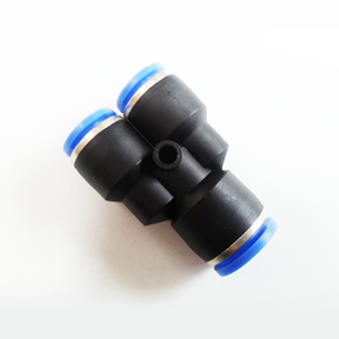

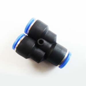
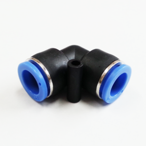
PW Reducer Y — One-Touch Pneumatic Reducer for Rapid, Tool-Free Tube Connections
The PW Reducer Y is a compact, one-touch pneumatic fitting engineered to provide rapid, reliable, and tool-free connections between compressed-air tubing of differing diameters and threaded ports. Designed as a PC-type body with hex-shaped inner and outer faces and pre-coated threaded ends, the PW Reducer Y is optimized for installations in confined spaces, quick maintenance, and leak-free assembly. This article provides an in-depth technical overview of the product, specifications, materials and build quality, key features, applications, comparisons with alternative fittings, benefits and limitations, and best practices for installation and maintenance.
Introduction
Pneumatic systems in industrial automation, machine tools, packaging lines, laboratory instrumentation, and building services routinely require flexible, reliable connections between tubing and threaded components. Reducer fittings are frequently used where tubing diameter transitions are needed or where a tube must be coupled to a port whose size differs from the available tube. The PW Reducer Y addresses these needs with a one-touch push-in design that minimizes assembly time and simplifies service procedures.
By enabling connection and disconnection in one to two seconds without tools, while maintaining vacuum and pressure capability adequate for most compressed-air systems, the PW Reducer Y reduces installation labor, limits leak sources, and supports compact routing in space-constrained installations. The hex-shaped body faces improve access for tightening in tight quarters, and the pre-applied seal coating on threaded joints helps ensure consistent sealing without additional tape or sealant during installation.
Technical Overview
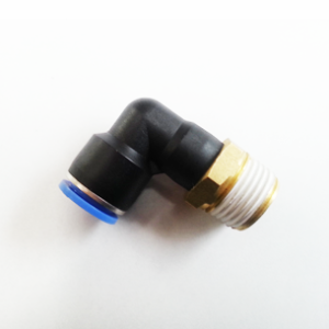
The PW Reducer Y is a push-in (one-touch) reducer fitting designed for compressed-air service. It combines a push-to-connect tube port with a threaded port in a compact PC-type body. The push-in side features a collet and internal sealing system that grip and seal the tube when the tube is fully inserted. The threaded side provides a secure mechanical and fluid connection to a mating port or component. Connections and disconnections are tool-free: push the tube fully into the fitting until it seats; to remove the tube, press the external sleeve (release collar) and withdraw the tube. Typical connection/disconnection takes 1–2 seconds.
Key functional capabilities:
- Tool-free, one-touch push-in tube connection
- Threaded port with pre-applied seal coating for simplified mounting
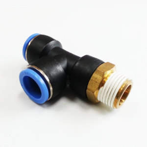
- Compact PC-type body with hex-shaped inner and outer faces for use in tight installations
- Designed for compressed-air service with pressure and vacuum capability
- Available in a wide range of metric and inch tubing sizes for mixed-diameter systems
Operational ranges and performance:
- Intended medium: compressed air only
- Maximum working pressure: 0–150 PSI (0–9.9 kgf/cm², approx. 0–990 kPa)
- Vacuum capability: down to -29.5 in Hg (approx. -750 mm Hg, ~10 Torr)
- Operating temperature range: 32–140 °F (0–60 °C)
The PW Reducer Y is most appropriate for pneumatic distribution lines, control circuits, and vacuum-assisted assemblies where fast, repeatable connections are needed and where installation space is limited.
Model Coding, Sizes and Porting Options
Model codification follows a compact format indicating the model type, tube outer diameter (φD) and thread size. Examples include formats such as “PC 06 1/8” or the equivalent PW-coded variants. Supported tubing sizes include both metric and inch series to accommodate mixed systems and international installations.
| Product Code (Example) | Tube Outer Diameter (φD) | Thread Size | Equivalent Inch Code |
|---|---|---|---|
| PW 06-04 | 6 mm | 1/8″ | PW 3/16-5/32 (example pairing) |
| PW 08-06 | 8 mm | 5/32″ | PW 1/4-5/32 |
| PW 10-08 | 10 mm | 3/16″ | PW 1/4-3/16 |
| PW 12-10 | 12 mm | 5/32″ | PW 5/16-5/32 |
| PW 16-12 | 16 mm | 1/4″ | PW 1/2-3/8 (inch variants available) |
Available metric tube outer diameters (φD): 4, 6, 8, 10, 12, 16 mm.
Available inch tube outer diameters: 5/32″, 3/16″, 1/4″, 5/16″, 3/8″, 1/2″.
Multiple thread-to-tube combinations are manufactured to allow selection of a reducer which fits both the tube OD and the mating threaded port size when routing or retrofitting mixed-diameter systems.
Specifications and Dimensions
The following specification table provides realistic, practical dimensions and performance characteristics representative of PW Reducer Y fittings. For final selection in engineered systems, refer to the manufacturer’s official datasheet for exact dimensions and tolerances for the specific model code.
| Parameter | Typical Value / Range | Notes |
|---|---|---|
| Operating medium | Compressed air (dry or lubricated) | Not rated for liquids or corrosive gases |
| Maximum working pressure | 0–150 PSI (0–9.9 kgf/cm², ≈0–990 kPa) | Do not exceed; pressure spikes should be limited |
| Vacuum capability | Down to -29.5 in Hg (≈ -750 mm Hg, ≈10 Torr) | Suitable for low vacuum applications typical in pick-and-place |
| Operating temperature | 32–140 °F (0–60 °C) | Dependent on seal polymer selection |
| Tube OD (metric) | 4, 6, 8, 10, 12, 16 mm | Choose matching tube OD |
| Tube OD (inch) | 5/32″, 3/16″, 1/4″, 5/16″, 3/8″, 1/2″ | Inch series available for imperial tubing |
| Thread sizes (examples) | 1/8″, 5/32″, 3/16″, 1/4″, 5/16″, 3/8″, 1/2″ | PT/NPT/BSP versions available depending on manufacturing |
| Connection time | ≈1–2 seconds | Push-in and release by sleeve |
| Material (body) | PC-type body (engineering polymer) | See Materials & Build Quality below |
| Seal materials (typical) | NBR (nitrile) / optional FKM/NBR blends | Choose per chemical and temperature needs |
| Collet / gripping ring | Stainless steel or plated carbon steel | Provides durable tube retention |
| Thread sealing | Pre-applied seal coating | No tape required; follow manufacturer instructions |
Materials and Build Quality
Understanding the materials and internal construction of the PW Reducer Y helps predict performance, durability, and compatibility with different pneumatic environments. The following breakdown describes typical materials used in push-in pneumatic fittings and explains the technical rationale for each choice. Note that specific materials and plating finishes may vary by manufacturer and model; always consult the product datasheet for the exact bill of materials for the unit you purchase.
Body: PC-Type Engineering Polymer
The term “PC-type body” refers to a body produced from a polycarbonate-like engineering polymer or a high-performance thermoplastic engineered for mechanical strength and dimensional stability. These polymers are chosen for their combination of properties:
- High mechanical rigidity and impact resistance for reliable assembly and repeated installation cycles.
- Good dimensional stability and low creep under load, which helps preserve thread engagement and sealing integrity in cyclic service.
- Resistance to the mechanical and thermal ranges typical of compressed-air systems (0–60 °C).
- Electrical insulation — a secondary benefit in some control environments.
Using an engineered polymer body reduces weight and the risk of corrosion compared with all-metal constructions, while also allowing for cost-effective manufacturing and complex internal geometries (collet recesses and spring housings).
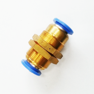
Threaded Portions: Brass or Plated Metal Inserts
Threaded connections are often implemented as brass or nickel-plated brass inserts molded or press-fit into the polymer body. These metallic thread inserts provide:
- Durable threads that resist wear from repeated installation/removal.
- Good machinability and reliable seal against mating metal ports.
- Compatibility with common thread seal coatings and sealants.
Some models may use stainless-steel threaded components for enhanced corrosion resistance in harsher environments.
Collet and Gripping Teeth: Stainless Steel or Plated Carbon Steel
The collet assembly contains a ring of teeth that mechanically grip the inserted tubing. Stainless steel is commonly specified for these teeth because it offers high fatigue resistance and corrosion resistance, maintaining retention performance over many connect/disconnect cycles.
Seals and O-Rings: Elastomeric Materials
The static and dynamic seals inside the push-in port are critical to leak-free performance. Typical elastomers include:
- Nitrile (NBR): Common for general-purpose compressed air; good resistance to lubricants and moderate temperatures.
- Fluorocarbon (FKM/Viton): Used for higher temperature tolerance and improved chemical resistance when oil mist or aggressive media may be present.
- EPDM: In some cases for water or steam resistance, though less common for compressed-air-only fittings.
Selecting the correct seal elastomer depends on the operating temperature, lubricant compatibility, and any specific chemical exposures in the system.
Internal Springs: Stainless Steel
Compression springs that bias the collet and seals are typically made from stainless steel to preserve spring force and resist relaxation and corrosion over long service life.
Thread Seal Coating
Threaded ends are pre-treated with a seal coating during manufacturing. This factory-applied layer is designed to fill thread roots and prevent leaks without the use of additional tapes or sealants. The coating choice and thickness are controlled to provide consistent performance while allowing disassembly if required.
Key Features — Technical Highlights
The PW Reducer Y packs several features that make it a practical choice for technical users. These characteristics are summarized below with notes on technical significance.
- One-touch push-in connection: Rapid, tool-free assembly and disassembly reduces installation time and downtime for maintenance.
- Compact PC-type body with hex-shaped faces: Enables use in space-constrained installations and facilitates torque application during threaded installation using standard spanners.
- Pre-applied seal coating on threads: Ensures consistent sealing during installation and minimizes the chance of cross-thread contamination from field-applied tapes.
- Wide size range: Supports both metric and inch tube sizes, enabling easy integration in global systems or systems with mixed tube OD.
- Pressure and vacuum capability: Rated for up to 150 PSI and vacuum down to approx. 10 Torr, providing flexibility for both pressurized and low-vacuum pneumatic applications.
- Durable gripping mechanism: Stainless steel collet teeth and engineered seal materials deliver long-term retention and leak resistance through many cycles.
- Fast connection/disconnection (≈1–2 seconds): Useful for assembly lines, modular fixturing, and field service where frequent reconfiguration occurs.
Use Cases and Applications
The PW Reducer Y is intended for compressed-air systems where fast, reliable, mixed-diameter connections are needed. The following sections outline common industrial and commercial use cases where the fitting brings measurable benefits.
1. Factory Automation and Robotics
Robotic end-effectors often incorporate pneumatic lines for actuation and vacuum gripping. The PW Reducer Y enables compact routing where actuator ports and tubing have different diameters. Quick release allows rapid tool change, maintenance, or reconfiguration of end-effectors without removing the entire piping harness.
2. Packaging Machines and Pick-and-Place Systems
High-speed packaging lines require rapid installation and frequent servicing. PW Reducer Y fittings reduce downtime by simplifying tube swaps and reconfigurations. Vacuum-capability makes them suitable for low-vacuum vacuum pads and pick-up heads.
3. Pneumatic Control Panels and Manifolds
In pneumatic control cabinets and valve manifolds, many small-diameter tubes must be routed and connected to solenoid valves and fittings. The PW Reducer Y’s hex faces and compact geometry make it easy to tighten on manifold outlets in close quarters while providing leak-resistant connections.
4. Laboratory and Instrumentation Applications
Laboratory gas lines and pneumatic test rigs benefit from quick-change tubing when experiments or test setups frequently change. The PW Reducer Y supports repeatable connection with minimal dead volume.
5. Maintenance, Retrofit and Field Service
For facilities upgrading systems or replacing components, the ability to connect dissimilar tube sizes easily accelerates retrofit work. The pre-treated threaded ends speed installation on existing ports without additional sealant application.
Comparison with Similar Products
Below is a technical comparison of the PW Reducer Y against alternative fitting types commonly encountered in pneumatic systems: standard push-in straight reducers, barbed reducers, quick-disconnect couplers, and threaded adapters. The table highlights typical advantages and trade-offs.
| Attribute | PW Reducer Y (One-touch) | Standard Push-In Straight Reducer | Barbed Reducer | Quick-Disconnect Coupler |
|---|---|---|---|---|
| Tool-free operation | Yes (push-in, sleeve release) | Yes (push-in) | No (requires clamp or crimp) | Yes (coupler/disconnect) |
| Threaded mounting | Yes (pre-coated) | Sometimes | Typically yes (barb on hose port) | Yes (often male/female threaded halves) |
| Space efficiency | High (compact, hex faces) | Moderate | Low (requires hose arching for clamps) | Moderate to high (couplers can be bulky) |
| Reusability | High (many cycles) | High | Limited (hose and clamp wear) | High (purpose-built for frequent disconnect) |
| Pressure rating (typical) | Up to 150 PSI | Up to 150 PSI | Depends on hose and clamp (variable) | Often similar to or higher than push-in connectors |
| Vacuum suitability | Yes (down to ~10 Torr) | Yes (model dependent) | Low to moderate | Good for many quick-disconnect vacuum couplers |
| Installation speed | Very fast (1–2s) | Fast | Slow (requires clamps or crimps) | Fast (but assembly of coupling halves needed) |
| Cost (per fitting) | Moderate | Low to moderate | Low | Higher (due to coupling mechanics) |
Summary interpretation: The PW Reducer Y offers the combined benefits of compactness, threaded mounting convenience, and one-touch operation. It frequently provides superior installation speed and cleanliness relative to barbed fittings and is more compact than many quick-disconnect couplers, while maintaining competitive pressure and vacuum capability versus standard push-in reducers.
Benefits and Limitations — Technical Evaluation
A balanced, technically oriented analysis helps determine whether PW Reducer Y is the right choice for a particular project.
Benefits
- Rapid installation and serviceability: One-touch push-in and sleeve-release reduce assembly time and downtime for maintenance or reconfiguration.
- Compact geometry: The PC-type body with hex-shaped faces is optimized for tight installations, allowing a spanner to be used in confined spaces.
- Sealed, reliable connections: The internal collet and elastomeric seals provide a leak-resistant junction appropriate for compressed-air circuits and modest vacuum use.
- Pre-coated threads: Factory seal coating on threads reduces the risk of thread leak paths and eliminates the need for field-applied sealing tape in most cases.
- Versatile sizing: A broad selection of metric and imperial tube sizes and thread variants facilitates integration into mixed systems or retrofits.
- Low maintenance: Durable materials and a robust collet minimize wear and reduce replacement frequency.
Limitations
- Media restriction: Designed for compressed-air service only; not recommended for liquids or corrosive gases unless explicitly certified by the manufacturer.
- Temperature and chemical limits: Operating temperature range (0–60 °C) and elastomer selection limit suitability for high-temperature or aggressive chemical environments. For elevated-temperature or special chemical exposure, confirm sealing material compatibility.
- Pressure spikes: While rated to 150 PSI, systems that experience frequent or severe pressure spikes above the rated maximum require pressure-limiting devices or alternative fittings rated for higher pressures.
- Compatibility with tubing variations: Optimal sealing and retention require tubing that meets manufacturer design tolerances for outer diameter and roundness. Damaged, undersized or oversized tubing may leak or be difficult to retain.
- Not all thread standards: Thread type (e.g., NPT, BSPP, PT) must be selected correctly for the mating port; mismatched thread standards will leak or damage threads.
Installation and Best Practices
Proper installation is essential to achieve the performance and reliability expected of PW Reducer Y fittings. Below are technical installation steps and best practices tailored for engineering and maintenance teams.
Pre-Installation Checklist
- Verify the fitting model code (tube OD and thread size) matches the tubing and mating port.
- Inspect tubes for the correct outer diameter, roundness, and absence of nicks or scratches.
- Confirm seals are correct for the operating temperature and any lubricants present in the compressed air (NBR is typical; choose FKM for higher temperature or incompatible oils).
- Ensure the mating port threads are clean, free of debris, and compatible with the pre-applied seal coating.
- Depressurize the system before making threaded connections (safe practice) unless specified otherwise by the manufacturer for live pressurized installation.
Threaded Installation
1. Thread the fitting into the mating port by hand until finger-tight.
2. Using an appropriate size wrench on the hex faces, tighten just enough to compress the pre-applied thread seal coating. Because the threads are pre-coated, avoid over-tightening which can damage threads or distort polymer bodies.
3. If manufacturer torque values are provided, follow them. If not, tighten until snug and perform a functional pressure test.
Tubing Preparation and Insertion
- Cut tubing squarely with a proper tubing cutter. Avoid diagonal cuts and jagged edges.
- Ensure the cut end is free of burrs and debris. If necessary, deburr using an appropriate tool.
- Mark insertion depth on the tube using the manufacturer’s insertion depth dimension; this ensures the tube is fully engaged with the internal seat for sealing.
- Push the tube into the fitting until it reaches the marked insertion depth or until it cannot be pushed any further (a positive stop will be felt).
- Optionally, perform a gentle pull test to validate that the collet teeth have engaged the tube properly.
Leak Testing
- After assembly and pressurization, perform a leak test. Use soapy-water bubble testing, an ultrasonic leak detector, or a pressure-decay test to verify leak-tight sealing.
- Address any detected leaks by checking tube insertion depth, ensuring correct tube OD and material, and verifying thread engagement.
Disconnection
Depressurize the line if possible. For service under live conditions, follow site safety procedures and verify the fitting design supports hot/under-pressure disconnection as needed. To remove the tube, depress the release sleeve (collar) fully and withdraw the tube while maintaining the sleeve depressed. Inspect the tube and fitting for damage before reassembly.
Troubleshooting Common Issues
- Leak at threaded joint: Confirm pre-applied coating was not compromised; verify thread type and engagement; re-install if necessary. Avoid adding extra tape unless recommended by the manufacturer.
- Tube slips out: Verify tube OD and hardness; check for damaged or vibrated tubing; confirm collet teeth are present and undamaged. Some situations may require a hose clamp or change to a different collet design if excessive axial loads are present.
- Difficulty inserting tube: Check for obstructions, debris, or damaged collet teeth. Confirm tube OD is within tolerance and tube end is cut square with no burrs.
- Frequent seal failures: Confirm seal material compatibility with compressed-air additives or system lubricants; consider upgrading to a different elastomer (e.g., FKM) if exposure is beyond NBR tolerance.
Maintenance and Care Guide
While the PW Reducer Y is designed for long life and minimal maintenance, a proactive maintenance regimen extends operational life and prevents unplanned downtime. The following maintenance practices are recommended for engineering and maintenance teams.
Routine Inspection
- Monthly: Visually inspect fittings for external damage, evidence of leaks (oil, dirt accumulation, dried residue), or signs of mechanical stress.
- Quarterly: Perform a leak check on critical lines and sample fittings using a soapy-water test or ultrasonic detector.
- Annually: Disassemble a representative sample of fittings to inspect internal seals and collet teeth for wear; replace seals as needed.
Cleaning
- Keep external surfaces free of dust, debris, and corrosive residues that can trap moisture.
- If cleaning is required, use a mild solvent compatible with the polymer body and elastomers (check manufacturer compatibility). Avoid aggressive solvents that may soften or swell seals.
Seal Replacement
- Replace O-rings or internal seals if they show evidence of hardening, cracking, or flattening which reduces sealing ability.
- Use manufacturer-specified replacement parts to maintain performance and preserve pressure/vacuum ratings.
Storage
- Store spare PW Reducer Y fittings in a clean, dry environment away from direct sunlight and extreme temperatures to prevent seal degradation.
- Avoid exposure to ozone sources or strong UV light which can degrade elastomers over time.
Selection Guidance and Engineering Considerations
Selecting the correct PW Reducer Y model for an engineered pneumatic system involves considering the following technical factors:
- Tubing material and OD tolerance: Ensure the tube outer diameter and material hardness match the model’s design intent (polyurethane, nylon, or polyethylene are typical). Some materials compress differently and affect retention force.
- Operating pressure and transient spikes: Confirm the maximum system pressure and consider installing surge protection or pressure relief if spikes can exceed 150 PSI.
- Temperature and chemical exposure: Choose the appropriate seal elastomer (NBR vs FKM) if operating near or above 60 °C or if oil/lubricant compatibility is a concern.
- Thread standard: Verify thread type (NPT, BSPT, BSPP, PT) and select the PW variant that matches the mating port to avoid cross-threading or leaks.
- Axial load: If the tubing is exposed to significant axial forces, consider supplemental mechanical retention (clamps) or select a fitting rated for higher pull-out force.
- Vacuum requirement: If using vacuum near the stated limit, validate system leakage and outgassing to achieve desired vacuum levels; confirm manufacturer vacuum rating for sustained vacuum duty.
Safety Considerations
- Always depressurize pneumatic lines before performing full disassembly unless the fitting is specified and certified for hot disconnect under pressure.
- Wear eye protection and appropriate PPE when disconnecting fittings under residual pressure to prevent ejected tubing or debris injuries.
- Ensure that fittings are not used outside their rated pressure and temperature limits; overpressurization can cause catastrophic failure.
- Do not use PW Reducer Y fittings for transport of flammable or corrosive gases unless they are explicitly certified for those media by the manufacturer.
Case Study Examples
The following hypothetical examples illustrate how the PW Reducer Y may be used in real-world engineering situations.
Case Study 1: Retrofit of a Packaging Line
A packaging line previously configured with barbed fittings and hose clamps was upgraded to reduce maintenance time and leaks. Replacing barbed-to-threaded transitions with PW Reducer Y fittings cut repair time by 60% and reduced leak-related downtime by 40% in the first year. The compact hex-face body allowed assembly within the original machine panspace where access was limited.
Case Study 2: Robotic End-Effector Modularization
A manufacturer designed a modular end‑effector interface for quick change-over across multiple robot cells. PW Reducer Y fittings provided secure, rapid pneumatic connections between the robot trailing cable and the end-effector, enabling tool changes in under 90 seconds. The fittings’ vacuum capability allowed integration of vacuum cups alongside actuators.
Ordering and Part Selection Checklist
To ensure correct ordering and reduce lead times, use this checklist when specifying PW Reducer Y fittings:
- Confirm tube outer diameter (metric or inch).
- Confirm mating port thread size and standard (NPT, BSPP, etc.).
- Confirm required seal material and temperature rating.
- Specify whether pre-coated threads are acceptable or if a bare-thread variant is required.
- Verify required quantity and any special packaging or labeling needs for assembly line integration.
- Request the manufacturer’s datasheet and performance curve for pull-out force, pressure drop, and vacuum leakage if system-level modeling is required.
Conclusion
The PW Reducer Y is a practical, technically sound solution for integrating differing tubing diameters and threaded components within compressed-air systems. Its one-touch push-in operation, compact PC-type body with hex-shaped faces, pre-applied thread seal coating, and broad size offerings make it well-suited to factory automation, packaging, robotics, instrumentation, and maintenance applications where speed, reliability, and space efficiency are priorities.
When selecting a PW Reducer Y, ensure compatibility of tubing material and size, confirm thread standard and seal elastomer for the intended operating environment, and follow best practices for installation and maintenance. Proper selection and use of the PW Reducer Y can reduce installation time, decrease leak frequency, and simplify field servicing, delivering measurable operational benefits in engineered pneumatic systems.
For precise mechanical drawings, dimensional tolerances, and certified performance metrics (pull-out force, pressure drop, and certified vacuum performance), consult the manufacturer’s technical datasheet for the specific PW Reducer Y model code you intend to install.
Appendix — Quick Reference Tables
Model Size Examples
| PW Model Code | Tube OD | Thread | Common Use |
|---|---|---|---|
| PW 04-02 | 4 mm | 1/8″ | Small pneumatic pilot lines, instrumentation |
| PW 06-04 | 6 mm | 1/8″ | Control lines to solenoid valves |
| PW 08-06 | 8 mm | 5/32″ | General distribution lines |
| PW 10-08 | 10 mm | 3/16″ | Actuator supply |
| PW 12-10 | 12 mm | 1/4″ | Main branch lines |
| PW 16-12 | 16 mm | 1/4″ or 5/16″ | High-flow main feeders |
Operating Parameters Quick Reference
| Parameter | Value |
|---|---|
| Medium | Compressed air only |
| Max Working Pressure | 0–150 PSI (0–9.9 kgf/cm², ≈0–990 kPa) |
| Vacuum Capability | Down to -29.5 in Hg (≈ -750 mm Hg, ≈ 10 Torr) |
| Operating Temperature | 32–140 °F (0–60 °C) |
If you would like, I can generate printable installation instructions or a customer-facing specification sheet (PDF-ready HTML) tailored to specific PW Reducer Y model codes and thread standards for your procurement and engineering teams.

Reviews
There are no reviews yet.