
 Tiếng Việt
SF Coupler ZNDC — Technical Guide, Specifications and Application Best Practices
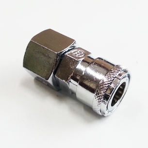
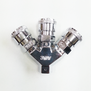
The SF Coupler ZNDC is a one-way quick coupler engineered for reliable, repeatable connections in compressed-air and fluid distribution systems. With a chrome‑plated zinc die‑cast (ZnDC) body, an integrated automatic internal valve and compatibility with air, water and oil, the SF Coupler ZNDC is targeted at industrial tool hookups, factory air lines and general-purpose fluid piping. This article provides a comprehensive, technical exploration of the SF Coupler ZNDC: design and function, detailed specifications and dimensions, materials and build quality, operational limits, real-world use cases, installation and maintenance procedures, troubleshooting, and a balanced comparison with alternative coupler types.
Introduction
Quick couplers are fundamental components in pneumatic systems, enabling fast, tool-free connections and disconnections between hoses, tools and supply lines. The SF Coupler ZNDC occupies a common niche for single‑direction (one‑way) coupling where the coupler body contains an automatic valve that opens only when a mating plug is inserted. This behavior minimizes loss of fluid or air during disconnect and reduces contamination risk. For maintenance teams, tool-room managers and systems designers, understanding the SF Coupler ZNDC’s capabilities and limitations is essential for correct selection, installation and lifecycle management.
Technical Overview
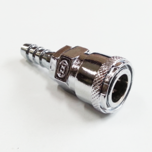
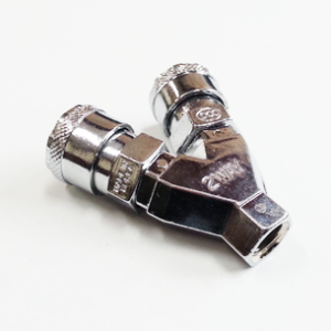
The SF Coupler ZNDC is a one‑way, inline quick coupler that integrates an automatic poppet-style valve in the coupler body. When the mating plug (socket) is inserted, it depresses the internal valve stem and allows flow through the coupler. Upon removal of the plug, the valve returns to its seated position under spring preload, sealing the coupler and preventing backflow or egress of the media.
Key functional characteristics:
- One‑way automatic shutoff: Internal valve prevents fluid/air escape when uncoupled.
- Quick connect/disconnect: Push‑to‑connect operation reduces connection time compared with threaded fittings.
- Multimedia compatibility: Rated for use with compressed air, water and hydraulic oils within specified pressure and temperature limits.
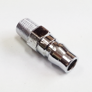
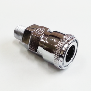
- Thread options: PT tapered thread variants are available — typical models are SF 20 (PT 1/4), SF 30 (PT 3/8) and SF 40 (PT 1/2).
The coupler is intended for general industrial service with maximum recommended working pressure up to 150 psi (approx. 0–990 kPa) and an operating temperature range of 0–60°C (32–140°F). These limits are conservative for the standard ZnDC body finish and nitrile (NBR) seals typically used in the baseline configuration.
Internal Mechanism
The SF Coupler ZNDC uses a spring-loaded poppet valve assembly. The poppet consists of a metal valve seat and an elastomeric sealing element. A compression spring maintains the valve in a closed position when no plug is present. On plug insertion, the plug nose pushes on the poppet stem, compressing the spring and opening the flow path. The mating plug geometry is important: it must engage the poppet properly to avoid partial opening, which can cause flow restriction or seal wear.
Specifications and Dimensions
The following table summarizes the technical specifications and typical physical dimensions for the SF Coupler ZNDC family. Values are nominal and should be confirmed with manufacturer datasheets for critical designs.
| Model | Thread (PT) | Nominal Bore | Maximum Working Pressure | Operating Temperature | Typical Flow @ 90 psi | Typical Cv | Body Length (mm) | Body Diameter (mm) | Weight (g) |
|---|---|---|---|---|---|---|---|---|---|
| SF 20 | PT 1/4 (BSPT 1/4) | 4.5 mm | 150 psi (≈ 990 kPa) | 0–60°C (32–140°F) | ≈ 25 SCFM (≈ 0.71 m3/min) | 0.4 | 48 mm | 22 mm | 80 g |
| SF 30 | PT 3/8 (BSPT 3/8) | 7.0 mm | 150 psi (≈ 990 kPa) | 0–60°C (32–140°F) | ≈ 50 SCFM (≈ 1.42 m3/min) | 0.9 | 58 mm | 26 mm | 140 g |
| SF 40 | PT 1/2 (BSPT 1/2) | 10.5 mm | 150 psi (≈ 990 kPa) | 0–60°C (32–140°F) | ≈ 85 SCFM (≈ 2.41 m3/min) | 1.5 | 70 mm | 34 mm | 260 g |
Notes:
- Flow figures (SCFM) are indicative at 90 psi inlet pressure with minimal downstream restriction. Actual flow depends on system piping, hoses, and downstream fittings.
- Nominal bore indicates the free internal passage when the coupler is open; it is useful for hydraulic flow calculations and pressure-drop estimation.
- Weights and dimensions are approximate for the ZnDC chrome‑plated variant; steel or brass bodies will be heavier and may have slightly different external dimensions.
Materials and Build Quality
The SF Coupler ZNDC emphasizes a balance between cost-effectiveness and functional performance by using a chrome-plated zinc die-cast (ZnDC) body. The chrome finish improves surface hardness, wear resistance and corrosion protection in moderate environments. It also provides a smooth aesthetic appearance that resists grime build-up on exterior surfaces.
Typical material stack for the standard SF Coupler ZNDC:
- Body: Zinc die‑cast (ZnDC) with a chrome plating finish.
- Valve components: Steel poppet stem and spring (zinc or nickel plated), seat retainer in steel.
- Seals: Nitrile rubber (NBR) elastomer for primary sealing (standard). Alternative elastomers such as Viton (FKM) available for higher temperature or oil-compatible variants.
- Plating: Chromium plating over a nickel undercoat in many production runs to enhance corrosion resistance and provide a smooth, hard surface.
Build quality considerations:
- Die-cast advantages: ZnDC allows complex geometries and consistent dimensional accuracy at low cost. The chrome plating adds localized hardness and abrasion resistance.
- Corrosion resistance: While chrome plating improves corrosion resistance, ZnDC is less robust than stainless steel or brass in aggressive external environments (marine, chemical exposure). For such environments, steel or brass variants are recommended.
- Seal longevity: NBR seals offer good performance with air and mineral oils but can degrade with some chemical fluids, high temperatures or long exposure to water. Specify alternative elastomers where compatibility is a concern.
Key Features
The SF Coupler ZNDC combines several features that make it a practical choice for many industrial applications. Highlights include:
- Automatic internal valve (one‑way): Minimizes loss of media when disconnected and reduces ingress of contaminants.
- Chromium-plated ZnDC body: Cost-effective construction with improved surface hardness and aesthetic finish.
- Multiple thread sizes: SF 20 (PT 1/4), SF 30 (PT 3/8), SF 40 (PT 1/2) for compatibility with common piping standards.
- Multimedia compatibility: Rated for air, water and oil service within specified limits.
- Simple push-fit operation: Fast, tool-free connections reduce downtime during tool changeovers or maintenance.
- Interchangeability: Compatible with common industry-standard plug geometries (verify mating dimensions for full interchangeability).
- Field serviceability: Internal components (seals, spring, poppet) can be replaced without specialized tooling in most cases.
Use Cases and Applications
The SF Coupler ZNDC is versatile across many sectors where quick, one-directional connections are required. Representative use cases include:
Pneumatic Tooling and Assembly Lines
In assembly plants and maintenance shops, the SF Coupler ZNDC provides quick attachment points for pneumatic tools such as impact wrenches, grinders, sanders and spray guns. One-way couplers ensure that lines remain sealed when tools are disconnected, reducing shop air loss and improving workplace cleanliness.
Factory Air Distribution Systems
Large facilities deploy the SF Coupler ZNDC at intermittent drop points and workstation manifolds. The one-way design assists in isolating sections during tool change-out and simplifies automated tool-change stations where tools are frequently swapped.
General Fluid Lines (Water and Oil)
Where low‑pressure water and oil lines require quick disconnection — for example, temporary flushing, test rigs, or portable lubrication stations — the SF Coupler ZNDC can be used provided the media and temperature remain within the rated limits.
Maintenance and Service Vehicles
Service carts and mobile rigs benefit from fast connect fittings for pneumatic supply and small hydraulic or lubrication circuits. The compact dimensions of SF 20 and SF 30 make them suitable for densely packed toolboxes.
Prototyping and Test Benches
In R&D and testing environments where lines are frequently rearranged, quick couplers expedite reconfiguration and minimize fluid loss during experiments.
Comparison with Alternative Couplers
Understanding how the SF Coupler ZNDC compares with other coupler types helps inform selection. The following table summarizes differences between the SF Coupler ZNDC (ZnDC), brass one-way couplers, stainless-steel couplers and universal two-way couplers.
| Attribute | SF Coupler ZNDC (ZnDC) | Brass One‑Way Coupler | Stainless‑Steel Coupler | Universal Two‑Way Coupler |
|---|---|---|---|---|
| Typical Cost | Low–Moderate | Moderate | High | Moderate–High |
| Corrosion Resistance | Moderate (chrome plated) | Good (brass resists many environments) | Excellent (316 SS best) | Varies with body material |
| Weight | Light | Moderate | Heavy | Moderate |
| Suitable for Harsh/Chemical Media | Limited | Better than ZnDC but limited | Best suited | Depends on material and seal |
| Leakage on Disconnect | Minimal (one‑way poppet) | Minimal | Minimal | May be bi‑directional unless two‑way valve present |
| Serviceability | Good — replace seals/spring | Good | Good | Good |
Selection guidance:
- Choose SF Coupler ZNDC where cost and weight are priorities and the environment is not highly corrosive.
- Specify brass bodies for better corrosion resistance in indoor humid or light chemical exposure.
- Use stainless steel for marine, chemical processing or food‑grade environments (confirm seal compatibility).
- Consider two‑way or universal couplers when both halves need to shut off independently or when bi‑directional flow control is required.
Benefits and Limitations
Benefits
- Fast operation: Push‑in connection reduces downtime and increases throughput in busy workstations.
- Reduced media loss: Automatic one‑way valve minimizes air and fluid losses when disconnected.
- Cost-effective: Zinc die‑cast bodies provide low-cost manufacturing while maintaining adequate mechanical strength for common industrial use.
- Compact and lightweight: Facilitates use on portable tools and mobile carts.
- Field serviceable: Replaceable internal components (seals and springs) extend service life and reduce lifecycle cost.
Limitations
- Corrosion susceptibility: ZnDC is less resistant to aggressive chemical or marine environments than brass or stainless steel.
- Temperature limits: Standard NBR seals and ZnDC bodies restrict operating temperatures to the stated range (0–60°C). Applications outside this range require alternative materials.
- Pressure ceiling: Maximum recommended working pressure is 150 psi. Systems operating at higher pressures must use dedicated couplers rated for those conditions.
- One‑way only: Does not inherently provide two-way shutoff; in some system designs a two-way coupler or manual valves may be required.
- Compatibility caution: Confirm plug/coupler geometry and thread standard (PT/BSPT) to avoid mismatches that can cause leaks or improper seating.
Installation and Best Practices
Correct installation ensures reliable performance and extends service life. Follow these practices when installing SF Coupler ZNDC units:
- Select proper thread type: The SF coupler family offers PT tapered threads (often equivalent to BSPT). Match thread type to mating piping and use appropriate sealing methods; do not mix PT with NPT without an adapter.
- Use proper sealant: Apply PTFE tape or a compatible liquid thread sealant to the male thread when installing the coupler into piping. Wrap PTFE tape in the direction of thread engagement to prevent unwrapping during installation. Avoid excess tape that could obstruct the internal flow passage.
- Torque control: Tighten to recommended torque values for the designated thread size. Over-tightening can crack die‑cast components; under-tightening can produce leaks. As a guideline, use the torque ranges below unless manufacturer data specifies otherwise:
- PT 1/4: 10–15 N·m
- PT 3/8: 18–25 N·m
- PT 1/2: 30–40 N·m
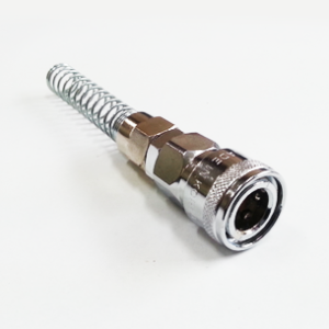
- Support piping and hoses: Avoid loading the coupler body with tensile or bending forces; use strain relief or hose clamps to reduce mechanical stress on connections.
- Orientation and accessibility: Install couplers where they are accessible for connection/disconnection and inspection. In high‑contamination areas, consider protective caps or filter screens upstream.
- Initial leak test: After installation, pressurize the system and perform a leak test. Use a soap solution or electronic leak detector to inspect threaded connections and the coupler body. Tighten or reseal as required.
Maintenance and Care Guide
A planned maintenance routine helps prevent failures and keeps the SF Coupler ZNDC operating efficiently. The following is a professional maintenance guide aimed at industrial maintenance teams.
Routine Inspection (Weekly to Monthly)
- Visually inspect couplers for external damage, chrome plating flaking or heavy corrosion.
- Check for visible leakage during normal operation and immediately after connection/disconnection cycles.
- Confirm that the locking and release mechanisms are operating smoothly and that the valve opens fully on plug insertion.
Preventive Maintenance (Quarterly or Based on Usage)
- Remove the coupler from service and disassemble according to manufacturer instructions. Inspect internal seals, springs and poppet for wear or deformation.
- Clean internal passages with a lint‑free cloth and a mild solvent compatible with the seal material (e.g., isopropyl alcohol for NBR, avoiding aggressive solvents that damage elastomers).
- Replace seals if hardened, cracked or swollen. Keep a spare parts kit (O‑rings/seats/springs) for each coupler size in service.
- Lightly lubricate moving metal-to-metal contact surfaces with a thin film of compressor-compatible lubricant or an approved grease; avoid petroleum-based oils that may affect seals unless they are oil‑compatible.
Seal Replacement Procedure (Typical)
- Depressurize and isolate the system. Ensure no residual pressure in the line.
- Unscrew the coupler from the line or remove it from the manifold.
- Disassemble retaining clip, spring and poppet as per the product manual.
- Remove and inspect sealing elements. Replace with new seals of specified material and durometer.
- Reassemble components in correct order and torque fasteners to specified values.
- Perform leak and functional test under the intended working pressure.
Storage and Handling
- Store couplers in dry, dust‑free conditions away from direct sunlight to avoid elastomer degradation.
- Use protective dust caps to keep internal passages clean when couplers are idle or transported.
- Label spare parts and match replacement seals to the proper model (SF 20/30/40) to avoid installation errors.
Troubleshooting Common Issues
Even with proper installation and maintenance, couplers can develop issues. The following troubleshooting guide helps diagnose common problems and recommended corrective actions.
Leak at Threaded Connection
- Likely cause: Insufficient thread sealant or damaged threads.
- Action: Depressurize, remove the coupler, clean threads, apply PTFE tape or appropriate thread sealant and reinstall to recommended torque. Replace fittings if threads are damaged.
Leak Between Coupler Body and Plug (During Use)
- Likely cause: Worn or damaged plug nose seal, damage to poppet seat, or debris preventing full engagement.
- Action: Inspect plug and coupler mating faces, clean or replace seals, and verify correct plug geometry and insertion depth.
Coupler Fails to Open (No Flow When Plug Inserted)
- Likely cause: Stuck poppet due to debris, corrosion or a damaged spring.
- Action: Disassemble, clean internal parts, check for spring fracture and replace components if required.
Difficulty Disconnecting Plug
- Likely cause: Corrosion or foreign particles in release mechanism, or insufficient lubrication.
- Action: Clean the release collar, inspect for bent components; lightly lubricate release surfaces with approved lubricant.
Premature Seal Failure
- Likely cause: Incompatible fluid, chemical exposure, or excessive temperature.
- Action: Determine service fluid and temperature exposure; switch to compatible elastomer (e.g., Viton) and re-evaluate operating limits.
Selection and Specification Checklist
When specifying SF Coupler ZNDC in a design or procurement specification, include the following items to ensure compatibility and reliable operation:
- Model number (SF 20, SF 30, SF 40) with thread size and gender (male/female).
- Thread type: confirm PT (BSPT) or specify adapter if NPT is used in the facility.
- Media type: air, water, oil — specify if aggressive fluids or additives are present.
- Temperature range expected in service and whether alternative seals (FKM/Viton, EPDM, PTFE) are required.
- Pressure rating requirement (ensure not to exceed 150 psi for standard SF Coupler ZNDC).
- Material preference: ZnDC chrome plated vs. brass vs. stainless steel depending on corrosion and hygiene requirements.
- Required flow capacity; use the nominal SCFM/Cv values to validate the coupler does not impose excessive pressure drop.
- Quantity of spare seal kits and recommended maintenance intervals.
Safety Considerations
Working with pressurized air and fluids carries inherent hazards. Observe these safety practices when using SF Coupler ZNDC units:
- Always depressurize and isolate lines before disconnecting a coupler or performing maintenance.
- Wear appropriate personal protective equipment (PPE): eye protection, gloves and hearing protection where noise is present during rapid depressurization.
- Beware of high-velocity ejection of hoses or fittings on sudden pressurized disconnection. Use secure hose clamps and retainers.
- Do not exceed the coupler’s rated pressure and temperature limits; overpressure can cause catastrophic failure and bodily injury.
- When changing media (e.g., switching from air to oil), flush the system to remove residual contaminants and verify seal compatibility.
Procurement and Lifecycle Costs
A lifecycle cost approach should consider the purchase price, installation, expected service life, maintenance intervals and spare parts. ZnDC bodies typically provide low initial cost but may require more frequent replacement in aggressive environments. Key cost drivers include:
- Material choice: stainless steel increases unit cost but reduces replacement frequency in harsh environments.
- Seal material: specialty elastomers (Viton, EPDM) raise initial cost but prevent premature failure in demanding media or higher temperatures.
- Downtime and maintenance: choose a coupler that minimizes unscheduled maintenance for critical processes.
Environmental and Regulatory Considerations
While the SF Coupler ZNDC is primarily a mechanical inline fitting, users should consider environmental controls and regulatory requirements applicable to their industry:
- For food, beverage or pharmaceutical applications, ensure materials and seals meet regulatory requirements for contact with potable water or foodstuffs. Standard ZnDC with chrome plating may not be acceptable; specify stainless and FDA-compliant seals where required.
- For outdoor or coastal installations, corrosion-resistant materials (brass or stainless steel) and additional protective coatings should be specified to avoid galvanic corrosion and plating failure.
- For explosive atmospheres or dust environments, ensure the coupler’s release and actuation do not create ignition sources; consult safety engineering standards relevant to the application.
Frequently Asked Questions (FAQ)
Q: Can SF Coupler ZNDC be used for high-temperature steam?
A: No. The standard SF Coupler ZNDC is rated for 0–60°C with NBR seals. Steam applications require higher temperature-rated materials and seal compounds (e.g., PTFE or silicone) and a body material capable of sustained elevated temperatures.
Q: Is the SF Coupler ZNDC compatible with hydraulic oil under pressure?
A: The coupler is usable with mineral-based oils within the pressure and temperature ratings, but it is not a high-pressure hydraulic coupling. For hydraulic systems above 150 psi, select a coupler specifically rated for hydraulic service.
Q: Are replacement seal kits available?
A: Yes — internal seal kits (NBR or alternate elastomers) and springs/retainers are typically offered as service parts. Maintain a parts inventory to support scheduled maintenance.
Conclusion
The SF Coupler ZNDC is a practical, cost-effective one-way quick coupler suitable for a broad range of compressed-air, water and light oil applications. Its chrome‑plated zinc die‑cast body provides a balance of affordability and adequate durability for many indoor industrial settings. The integrated automatic internal valve minimizes media loss and simplifies daily operations where frequent tool exchanges occur. Correct model selection (SF 20, SF 30, SF 40), adherence to installation torque and thread standards (PT/BSPT), and a proactive maintenance program that includes periodic seal inspection and replacement will maximize service life and reliability.
For environments with aggressive chemicals, high humidity, elevated temperatures or elevated pressure requirements, evaluate brass or stainless-steel variants and alternative seal materials such as Viton. When specified and maintained correctly, the SF Coupler ZNDC offers dependable performance and a low total cost of ownership for many pneumatic and light fluid distribution systems.
If you require specific engineering drawings, pressure‑drop curves, or compatibility testing for a specialized fluid or temperature regime, consult the manufacturer’s technical datasheets or contact a qualified applications engineer to verify suitability for your exact use case.

Reviews
There are no reviews yet.